8
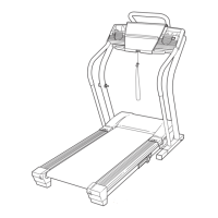
6. Set the Left Upright Spacer (76) on the Base
(83). With the help of a second person, insert
two 3/8” x 5” Bolts (6) with two 3/8" Star
Washers (9) into the Left Upright (74) and set
the Left Upright into the Left Upright Spacer. If
necessary, use a rubber mallet on top of the Left
Upright to make sure that the Upright is fully in-
serted into the Left Upright Spacer.
Partially tighten the 3/8” x 5” Bolts (6) by turning
them several times; do not fully tighten the
Bolts yet.
Press a Base Endcap (77) into the Base (83).
With the help of a second person, tip the tread-
mill so that the Base (83) is flat on the floor.
76
74
6
83
77
6
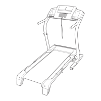
5. With the help of a second person, carefully tip
the treadmill onto its right side. Partially fold the
Frame (56) so the treadmill is more stable;
do
not fully fold the Frame yet.
Remove and discard the two indicated bolts (A)
and the shipping bracket (B).
Attach a Base Pad (81) to the Base (83) in the
location shown with a #8 x 1" Tek Screw (2) and
a Base Pad Spacer (13). Then, attach another
Base Pad (81) with only a #8 x 1" Tek Screw (2).
Remove the 3/8" Nut (8), the 3/8" x 2" Bolt (4),
and the shipping bracket (C) from the Base (83).
Attach a Wheel (84) with the Bolt and the Nut
that you just removed. Do not overtighten the
Nut; the Wheel must turn freely. Discard the
shipping bracket.
5
83
B
A
84
56
4
8
C
81
2
81
13
2
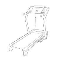
4. Set the Right Upright Spacer (79) on the Base
(
83).
B
e careful not to pinch the Upright Wire
(38).
With the help of a second person, insert
two 3/8” x 5” Bolts (6) with two 3/8" Star
Washers (9) into the Right Upright (78) and set
t
he Right Upright into the Right Upright Spacer.
If necessary, use a rubber mallet on top of the
Right Upright to make sure that the Upright is
fully inserted into Spacer.
Partially tighten the 3/8” x 5” Bolts (6) by turning
them several times; do not fully tighten the
Bolts yet.
Press a Base Endcap (77) into the Base (83).
79
7
8
77
6
4
83
38
9
9
 Loading...