7
ASSEMBLY
• Assembly requires two persons.
• Placeallpartsinaclearedareaandremovethe
packing materials. Do not dispose of the packing
materialsuntilyounishallassemblysteps.
• Aftershipping,theremaybeanoilysubstance
on the exterior of the treadmill. This is normal. If
there is an oily substance on the treadmill, wipe
it off with a soft cloth and a mild, non-abrasive
cleaner.
• Left parts are marked “L” or “Left” and right parts
are marked “R” or “Right.”
• To identify small parts, see page 6.
• Assemblyrequiresthefollowingtools:
the included hex key
one adjustable wrench
one Phillips screwdriver
To avoid damaging parts, do not use power tools.
1. Make sure that the power cord is unplugged.
Attach the Left Wheel Cap (96) to the Base (94)
with two #8 x 3/4" Screws (2).
Attach the Right Wheel Cap (not shown) to
the Base (94) in the same way.
1
96
94
2
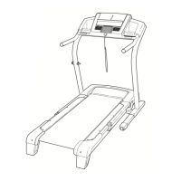
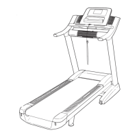
2. Pull the Upright Wire (81) and the base ground
wire (A) through the indicated hole in the Base
(94) using the plastic tie.
Attach the base ground wire (A) to the Base (94)
with a #8 x 1/2" Ground Screw (10).
Press the Grommet (77) into the square hole in
the Base (94).
See the inset drawing. Cut the plastic tie near
the Upright Wire (81). Be careful not to dam-
age the Upright Wire.
81
2
Tie
94
Hole
Square
Hole
10
A
77
Cut
81
Tie
 Loading...