Hardware Installation and Setup
3-20
Part 1120130
E 2011 Nordson Corporation
To wire inputs/outputs to the melter
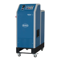
See Figure 3‐14.
1. A female quick connector (32 positions + PE) is located on the melter
right panel. Route a signal cable from the control equipment to the melter
through a male quick connector (32 positions + PE). The male quick
connector has a PG-21 strain relief to fasten the signal cable. I/O
connector designation: -17X21 Function: transmits the digital
input/output signals and key-to-line signal between the parent machine
and the Nordson melter.
NOTE: Use a signal cable suitable for NEC class1 remote control and
signaling circuits. To reduce the possibility of electrical shorting, route the
cable so that it does not touch nearby circuit boards.
2. Connect each pair of input and output wires to the appropriate terminals
on I/O connector. Refer to table below for the terminal numbers that
correspond to each input.
Figure 3-14 Location of the quick connector (-17X21) for connecting input/output wiring
 Loading...
