N/IM/en 8.446.307.01
Our policy is one of continued research and development. We therefore reserve the right to amend,
without notice, the specifications given in this document. © 2014 IMI International s.r.o.
1/14 1999-IM8150b
B38 - Installation & Maintenance Instructions
Technical Data
Fluid: Compressed air
Maximum pressure:
Stainless steel
Manual drain: 31 bar (450 psig)
Automatic drain: 17 bar (245 psig)
Operating temperature*:
-40° ... +80°C (-40° ... +176°F)
* Air supply must be dry enough to avoid ice formati-
on at temperatures below +2°C (+35°F).
Particle removal: 5 μm or 25 μm filter element
Air quality: Within ISO 8573-1, Class 3 and Class 5
(particulates)
Typical flow with 7 bar (100 psig) inlet pressure, 1
bar (15 psig) set pressure and 0,05 bar (1 psig) droop
from set: 8 dm3/s (17 scfm)
Automatic drain connection: 1/4“ PTF
Automatic drain operating conditions
(float operated):
Bowl pressure required to close drain: Greater
than 0,3 bar (5 psig)
Bowl pressure required to open drain:
Less than 0,2 bar (3 psig)
Minimum air flow required to close drain:
1 dm3/s (2 scfm)
Gauge ports:
1⁄4“ as per main ports
Materials:
Body: Stainless steel
Bonnet: Stainless steel
Bowl: Stainless steel
Adjusting screw: Stainless steel
Element
5 μm: Stainless steel
25 μm: Vyon
Elastomers: Synthetic rubber
Diaphragm insert: Acetal resin, stainless steel and
nitrile
Other parts stainless steel
Replacement items
Service Kit (includes items circled on exploded view):
Relieving
2 bar R38-100R
4 & 7 bar R38-101R
10 bar R38-102R
Non relieving
2 bar R38-100NR
4 & 7 bar R38-101NR
10 bar R38-102NR
Filter section
5 μm stainless steel B38-100S(5)
25 μm stainless steel B38-100S(25)
5 μm viton and stainless steel B38-150S(5)
25 μm stainless steel B38-150S(25)
Auto drain (replacement) 3000-90
Panel Mounting Dimensions
Panel mounting hole diameter: 42 mm (1,65”)
Panel thickness: 0 .... 6 mm (0” ... 0,24”)
Installation
1. Shut off air pressure. Install filter/regulator in air
line -
• vertically (bowl down),
• with air flow in direction of arrow on body,
• upstream of lubricators and cycling valves,
• as close as possible to the device being serviced.
2. Connect piping to proper ports using pipe thread
sealant on male threads only. Do not allow sealant
to enter interior of unit.
3. Install a pressure gauge or plug the gauge ports.
Gauge ports can also be used as additional outlets
for regulated air.
Adjustment
1. Before applying inlet pressure to filter/regulator,
turn adjustment (2) counterclockwise to remove
all force on regulating spring (7).
2. Apply inlet pressure, then turn adjustment (2)
clockwise to increase and counterclockwise to
decrease outlet pressure setting.
3. Always approach the desired pressure from a
lower pressure. When reducing from a higher to a
lower setting, first reduce to some pressure less
than that desired, then bring up to the desired
pressure.
NOTE
With non-relieving filter/regulators, make
pressure reductions with some air flow in the
system. If made under no flow (dead-end)
conditions, the filter/regulator will trap the over-
pressure in the downstream line.
4. Once required pressure is achieved tighten
locknut (3) to lock setting.
Servicing
1. For manual drain models, regularly open drain
to expel accumulated liquids. Keep liquids below
element retainer (13).
2. At approximately 6 month intervals it is advisable
to remove the bowl assembly by removing the
securing screws (4) and unscrewing the element
retainer (13) to remove the element (15) for
inspection. Since the direction of air flow is from
the inside of the element to the outside, a clean
exterior is not an an indication of freedom from
contamination. If the filter element shows
evidence of blockage, replace with new element.
Clean the element retainer (13) and the upper and
lower gaskets (14) before replacing the filter
element –avoiding excessive overtightening of the
retainer. Inspect the bowl O-ring (16) for damage
and renew if necessary.
3. Clean or replace filter element when dirty.
Disassembly
1.Filter/Regulator can be disassembled without
removal from air line.
2. Shut off inlet pressure. Reduce pressure in inlet
and outlet lines to zero.
3. Turn adjustment screw fully counterclockwise.
4. Disassemble in general accordance with the item
numbers on exploded view. Do not remove the
drains unless replacement is necessary. Remove
and replace drains only if they malfunction.
Cleaning
1. Rinse and dry parts. Blow out internal passages
in body (30) with clean, dry compressed air. Blow
air through filter element (15) from inside to
outside to remove surface contaminants.
2. Inspect parts. Replace those found to be
damaged.
Assembly
1. Lubricate threads and nose of adjusting screw
(2) at regular intervals with suitable grease eg.
Speerol APT2.
2. Lubricate seals (16, 36, 37) with light coat of good
quality grease.
3. Assemble the unit as shown on the exploded view.
4. Torque Table
Item Nm (Inch-Pounds)
4 (screws, stainless steel model) 7,3/3,3 (66/30)
* Outlet pressure can be adjusted to pressures in excess of, and less than, those specified. Do not use these units to control pressures outside of the specified ranges.
Options
0....Stainless steel, relieving
1....Stainless steel, non-relieving
2....Stainless steel, relieving with bracket and panel nut
3....Stainless steel, non-relieving with bracket and panel nut
4....Stainless steel, relieving with panel nut
5....Stainless steel, non-relieving with panel nut
6....Stainless steel, relieving with handwheel and panel nut
7....Stainless steel, non-relieving with handwheel and panel nut
8....Stainless steel, relieving with handwheel, bracket and panel nut
9....Stainless steel, non-relieving with handwheel, bracket and panel nut
Drain
A....Automatic
B....Manual
Material
4....Stainless steel (standard)
5....Stainless steel and FPM
Spring (Outlet Pressure Range) *
C....0,04 ... 2 bar (0.6 ... 30 psig)
F ....0,07 ... 4 bar (1 ... 60 psig)
K....0,25 ... 7 bar (3,6 ... 100 psig)
M...0,5 ... 10 bar (7.2 ... 150 psig)
Stainless steel instrument regulator
B38 – 2˙˙ – ˙˙˙A
Element
1 5 μm
2 25 μm
1
2
3
4
5
6
7
8
38
32
36
37
30
16
14
15
14
13
11
17
19
4
4
20
21
18
33
34
35
Our policy is one of continued research and development. We therefore reserve the right to amend,
without notice, the specifications given in this document. (1999-xxxxb) © 2020 IMI International s.r.o.
4/19
IM/en 8.446.307.01
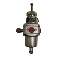
B38 - Stainless Steel, Precision Filter/Regulator
Installation & Maintenance Instructions
2. Connect piping to proper ports using pipe thread
sealant on male threads only. Do not allow sealant to
enter interior of unit.
3. Install a pressure gauge or plug the gauge ports.
Gauge ports can also be used as additional outlets for
regulated air.
ADJUSTMENT
1. Before applying inlet pressure to ilter/regulator, turn
adjustment (2) counterclockwise to remove all force on
regulating spring (7).
2.
Apply inlet pressure, then turn adjustment (1) clockwise to
increase and counterclockwise to decrease outlet pressure
setting.
3. Always approach the desired pressure from a lower
pressure. When reducing from a higher to a lower
setting, irst reduce to some pressure less than that
desired, then bring up to the desired pressure.
NOTE
With non-relieving ilter/regulators, make pressure
reductions with some air low in the system. If made
under no low (dead-end) conditions, the ilter/
regulator will trap the over-pressure in the downstream
line.
4. Tighten locknut (3) to lock pressure setting.
SERVICING
1. For manual drain models, regularly open drain to
expel accumulated liquids. Keep liquids below element
retainer (13).
2. At approximately 6 month intervals it is advisable to
remove the bowl assembly by removing the securing
screws (4) and unscrewing the element retainer (13)
to remove the element (15) for inspection. Since the
direction of air low is from the inside of the element
to the outside, a clean exterior is not an indication of
freedom from contamination. If the ilter element
shows evidence of blockage, replace with new element.
Clean the element retainer (13) and the upper and
lower gaskets (14) before replacing the ilter element
–avoiding excessive overtightening of the retainer.
Inspect the bowl O-ring (16) for damage and renew if
necessary.
3. Clean or replace ilter element when dirty.
DISASSEMBLY
1. Filter/regulator can be disassembled without removal
from air line.
2. Shut off inlet pressure. Reduce pressure in inlet and
outlet lines to zero.
3. Turn adjustment screw fully counterclockwise.
4. Disassemble in general accordance with the item
numbers on exploded view. Do not remove the drain
unless replacement is necessary. Remove and replace
drain only if it malfunctions.
CLEANING
1. Rinse and dry parts. Blow out internal passages in body
(30) with clean, dry compressed air. Blow air through
ilter element (15) from inside to outside to remove
surface contaminants.
2. Inspect parts. Replace those found to be damaged.
TECHNICAL DATA
Fluid: Compressed air
Maximum pressure:
Manual drain: 31 bar (450 psig)
Automatic drain: 17 bar (247 psig)
Operating temperature*: -40° ... +80°C
(-40° ... +176°F)*
* Air supply must be dry enough to avoid ice formation at
temperatures below +2°C (+36°F).
Particle removal: 5 m or 25 m ilter element
Air quality: Within ISO 8573-1, Class 3 and Class 5
(particulates)
Typical low with 7 bar (102 psig) inlet pressure, 1 bar (14.5
psig) set pressure and 0,05 bar (0,7 psig) drop from set: 8
dm3/s (17 scfm)
Automatic drain connection: 1/4“ PTF
Automatic drain operating conditions
(loat operated):
Bowl pressure required to close drain: Greater
than 0,3 bar (4,4 psig)
Bowl pressure required to open drain:
Less than 0,2 bar (3 psig)
Minimum air low required to close drain:
1 dm3/s (2 scfm)
Gauge ports:
1⁄4“ as per main ports
Materials:
Body: Stainless steel
Bonnet: Stainless steel
Bowl: Stainless steel
Adjusting screw: Stainless steel
Element
5 m: Stainless steel
25 m: Vyon
Elastomers: Synthetic rubber
Diaphragm insert: Acetal resin, stainless steel and nitrile
Other parts stainless steel
REPLACEMENT ITEMS
Service Kit (includes items circled on exploded view):
Relieving
2 bar R38-100R
4 & 7 bar R38-101R
10 bar R38-102R
Non relieving
2 bar R38-100NR
4 & 7 bar R38-101NR
10 bar R38-102NR
Filter section
5 m stainless steel B38-100S-5
25 m stainless steel B38-100S-25
5 m viton and stainless steel B38-150S-5
25 m stainless steel B38-150S-25
Auto drain (replacement) 3000-90
PANEL MOUNTING DIMENSIONS
Panel mounting hole diameter: 41 mm (1.61”)
Maximum panel thickness: 0 ... 6 mm (0 ... 0.24”)
INSTALLATION
1. Shut off air pressure. Install ilter/regulator in air line
• vertically (bowl down),
• with air low in direction of arrow on body.
• upstream of lubricators and cycling valves,
• as close as possible to the device being serviced.
* Outlet pressure can be adjusted to pressures in excess of, and less than, those speciied. Do not use these units to control
pressures outside of the speciied ranges.
Material
4 Stainless steel
(standard)
5 Stainless steel and FPM
Spring (Outlet Pressure Range) *
C 0,04 ... 2 bar (0,5 ... 29 psig)
F 0,07 ... 4 bar (1 ... 58 psig)
K 0,25 ... 7 bar (3,6 ... 102 psig)
M 0,4 ... 10 bar (5,8 ... 145 psig)
Thread Form
A PTF
Element
1 5 m
2 25 m
Drain
A Automatic
B Manual
B38 - HHH - HHHH
Port
2 1/4”
Diaphragm
0 Stainless steel, relieving
1 Stainless steel, non-relieving
2 Stainless steel, relieving with bracket and panel nut
3 Stainless steel, non-relieving with bracket and panel nut
4 Stainless steel, relieving with panel nut
5 Stainless steel, non-relieving with panel nut
6 Stainless steel, relieving with handwheel and panel nut
7 Stainless steel, non-relieving with handwheel and panel nut
8 Stainless steel, relieving with handwheel, bracket and panel nut
9 Stainless steel, non-relieving with handwheel, bracket and panel nut