Heat Exchanger Replacement Procedure
Diagram
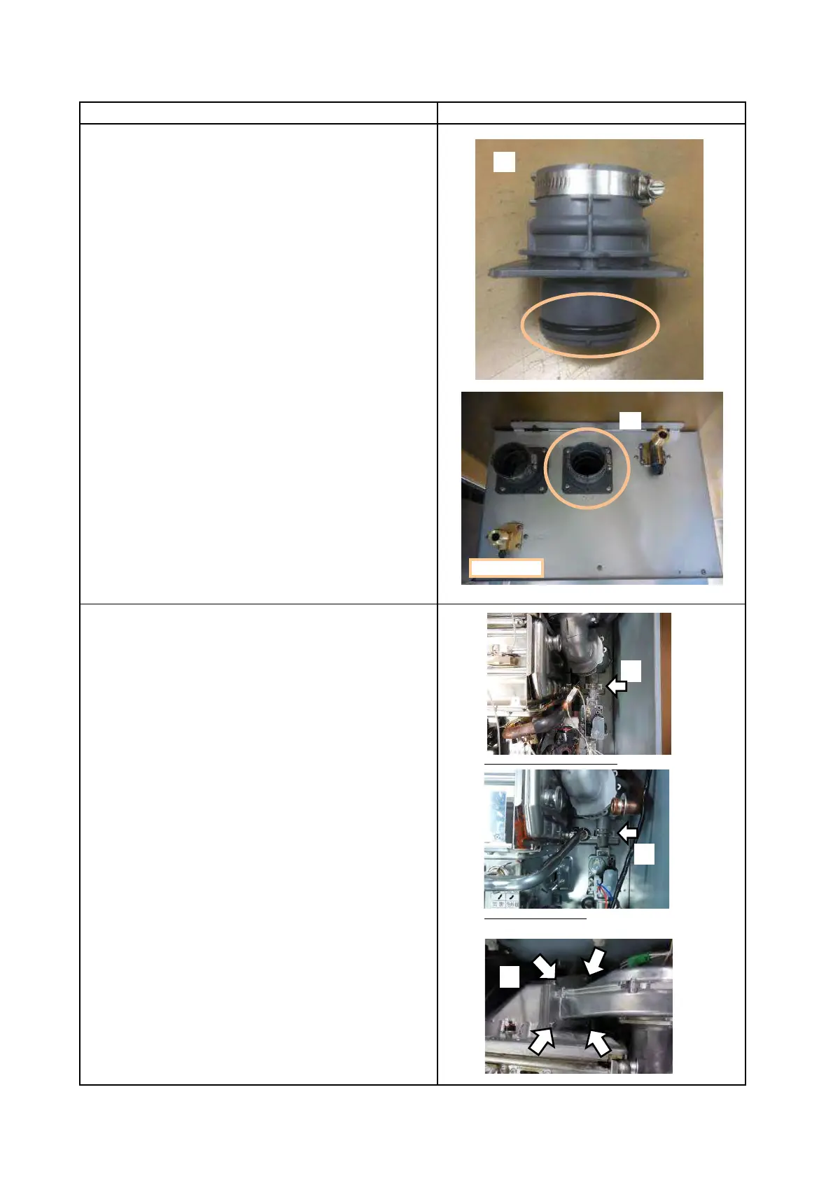
(3) Replace the O-Ring of Exhaust Flue with new one.
(4) Attach Exhaust Flue to the case
with 4 new screws(M4×12).
17. Attach Fan Motor and Venturi assembly
(1) Attach the Fan Motor and Venturi assembly.
Attach "C" Clamp at the bottom of Venturi.
(2) Secure the Venturi to the Burner Chamber by tightening
the 4 screws(M5×12) removed in Step 6.
The screws need only to be hand tightened and
should not be tightened using a drill.
First, insert and tighten 4 screws, but do not
fully tighten these screws.
Once all screws are inserted, proceed to
completely tighten 4 screws.
NOTE: When tightening the screws, be certain to not
apply excess force. Excess force can strip out the original
holes and screws. Keep the Fan motor in horizontal.
It makes easier to tighten the screws correctly.
Page 18
Procedure
(3)
(2)
(1)
EZ111DV/EZ98DV or NCC199CDV
(1)
NRCB199DV/NRCB180DV