Heat Exchanger Replacement Procedure
Diagram
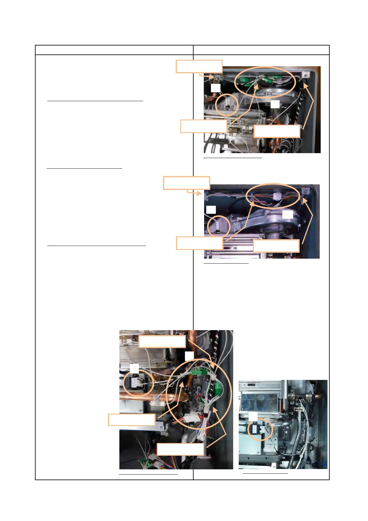
19. Plug all wires that attach to Wiring Harness
(1) Plug High Limit Switch.
(2) For EZ111DV/EZ98DV or NCC199CDV
Plug 4 Freeze Prevention Heaters,
Fan Motor,
(NCC199CDV:1 Freeze Prevention Heater. ),
Thermistor - Primary Heat Exchanger Outlet,
Thermistor - Exhaust
and hook Wiring Harness to 2 Wire Clamps.
For NRCB199DV/NRCB180DV
Plug Fan Motor and Thermistor - Exhaust.
and hook Wiring Harness to 2 Wire Clamps.
(3) Hook Wiring Harness by using Wire Clamps.
(4) Plug Igniter.
(5) Only EZ111DV/EZ98DV or NCC199CDV
Plug 6 Freeze Prevention Heaters,
Water Servo - Bypass,
Gas Valve
Thermistor - Primary Heat Exchanger Outlet,
High Limit Switch
(NCC199CDV:2 High Limit Switches. )
and bundle Wiring Harness with 3 Cable Ties.
Page 21
Procedure
EZ111DV/EZ98DV or NCC199CDV
(3) Wire Clamp
(3) Wire Clamp
(3) Wire Clamp
NRCB199DV/NRCB180DV
(3) Wire Clamp
(3) Wire Clamp
(3) Wire Clamp
(5)
(4)
Cable Tie
Cable Tie
Cable Tie
EZ111DV/EZ98DV or NCC199CDV
NRCB199DV/NRCB180DV
(4)
 Loading...