Heat Exchanger Replacement Procedure
Diagram
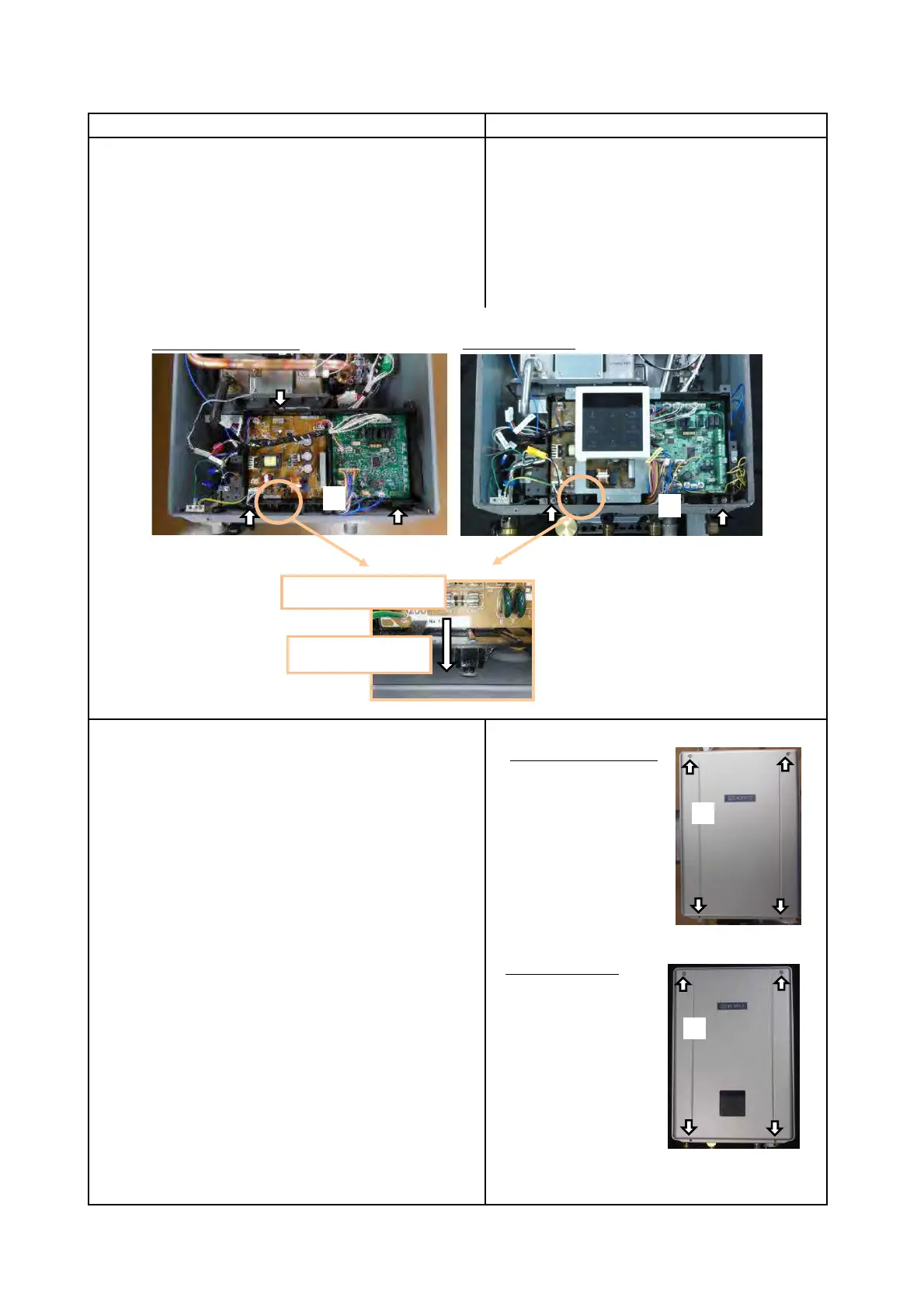
22. Attach Front Cover
(1) Attach Front Cover with 4 screws w/ washer(M4×12).
Page 23
NRCB199DV/NRCB180DV: 2 screws
Procedure
21. Attach Circuit Board
(1) Attach Circuit Board with the screws(M4×12)*.
* EZ111DV/EZ98DV or NCC199CDV: 3 screws
NRCB199DV/NRCB180DV
EZ111DV/EZ98DV or NCC199CDV
Enlarged view
Put into the hole
(1)
EZ111DV/EZ98DV or NCC199CDV
NRCB199DV/NRCB180DV
(1)