6
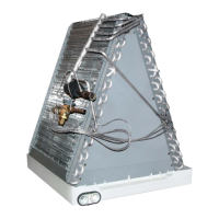
Figure 2. C84DA Coil Dimensions
F
H
12 1/8”
19 1/2”
W
2 1/2”
1 3/8”
Table 1. Coil Specifications
C84DA- X24 X30 X36 X42 X43 X48 X49
Nominal Capacity (BTU/hour) 24,000 30,000 36,000 42,000 42,000 48,000 48,000
Nominal Airflow (CFM) 800 1,000 1,200 1,400 1,400 1,600 1,600
W - Width (in.) 18 1/8 18 1/8 18 1/8 18 1/8 18 1/8 18 1/8 18 1/8
H - Height (in.) 18 18 18 18 25 25 29
D - Depth (in.) 19 1/2 19 1/2 19 1/2 19 1/2 19 1/2 19 1/2 19 1/2
Connection - Liquid Line (in.) 3/8 3/8 3/8 3/8 3/8 3/8 3/8
Connection - Suction Line (in.) 3/4 3/4 3/4 7/8 7/8 7/8 7/8
NOTES:
1. Individual restrictors are available by part number - PN664*** (where *** represents the size).
Example: 664103 is a restrictor 0.103 in diameter.
2. Refer to sales specification sheets for Listed/Certified combinations of equipment and required accessories.
3. Refer to the current AHRI directory for certified ratings of split systems.
COIL SPECIFICATIONS & DIMENSIONS
 Loading...