2
Installation with Mounting Screws
If your existing light switch is a decorator type or toggle switch with screw holes
that line up with WA00Z-1, you may secure the WA00Z-1 using two screws.
Installation on a Single-gang Switch
1. Remove the mounting screws on the existing wall plate
2. Remove the existing wall plate from the in-wall switch.
3. Place the bottom case of WA00Z-1 on the in-wall switch. Make sure the
existing switch is in the ON position.
4. Tighten the mounting screws and secure the bottom case of WA00Z-1
5. Place the wider faceplate on the WA00Z-1 main unit.
Installation on a Multi-gang Switch
1. Remove the mounting screws on the existing wall plate that you wish to
cover (do NOT remove the screws on other switch nor the wall plate).
2. Place the WA00Z-1 main unit on top of the existing faceplate. Make sure
the existing switch is in ON position.
3. Secure the WA00Z-1 main unit to the existing wall plate using the included
longer mounting screws.
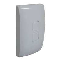
4. Snap on the narrower faceplate on the WA00Z-1. Make sure the two buttons
are fl ush with the surface of the faceplate.
IMPORTANT NOTE:
Please note that it is extremely important to follow the installation procedure
to have WA00Z-1 operate properly with your home gateway. Installation of
WA00Z-1 ensures that the power to the Z-Wave device always remains ON.
Without the electrical power to the Z-Wave device, it cannot be turned ON
remotely nor function as a signal repeater to maintain proper Z-Wave network.
PROGRAMMING
Adding to a network:
Refer to your Controller operating instructions to add this switch under the
command of the Wireless Controller.
1. With your Controller in Discovery or Add Mode, press either button on the
WA00Z-1. The green LED should fl ash twice.
2. You should see an indication on your Controller that the “device was added”
to the network.
3. The device will appear in the list of Switches. It should display as a switch.
✓ NOTE: If the Controller/Gateway shows the addition failed or the WA00Z-1
LED fl ashed red, repeat Steps 1-3.
✓ NOTE: If you have trouble adding the WA00Z-1 to a group it may be that
the Home ID and Node ID were not cleared from it after testing. You must
fi rst “RESET UNIT” to remove it from the network. Although adding it to a
group includes it in the network, removing it from a group does not remove it
from the network. If removed from a group, it functions as a repeater (only).
“RESET UNIT” removes it completely from the network.
To Reset Unit (If Required):
In the event that your primary Controller is lost or otherwise inoperable, to reset
the WA00Z-1 and clear all network information, follow these steps:
1. Press the top switch fi ve times and then press the bottom switch fi ve times
within fi ve seconds.
2. The LED will fl ash seven times to indicate that a Reset is taking place.
Removing from a network:
The WA00Z-1 can be removed from the network by the Controller/Gateway.
Refer to the Controller operating instructions for details.
1. Set the Controller into Removal Mode and follow its instruction to delete the
WA00Z-1 from the Controller.
2. Remove the switch by pressing either button on the WA00Z-1. The LED will
fl ash twice indicating that it has been removed.
3. You should see an indication on your Controller that the “device was
removed” from the network.
 Loading...