42 Site planning
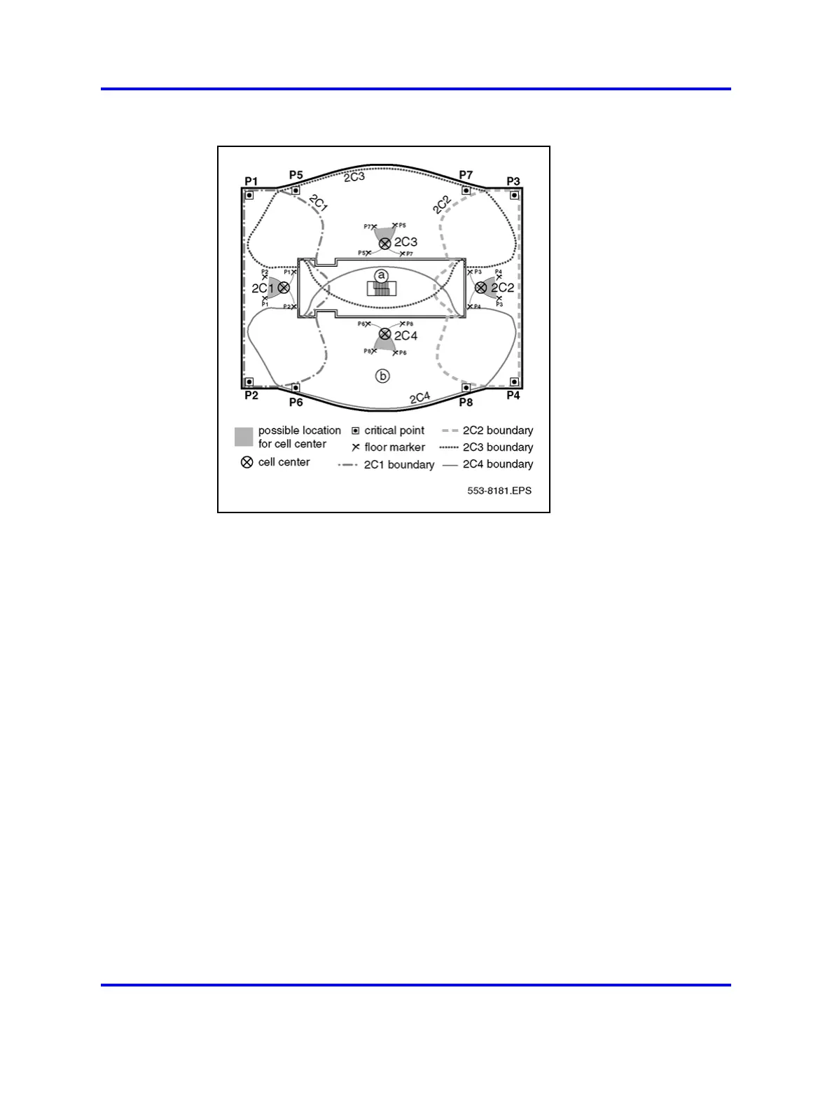
Figure 14
Points, centers, and boundaries on the floor plan
Figure 14 "Points, centers, and boundaries on the floor plan" (page
42) shows a typical floor plan marked-up after determining subsequent cell
boundaries. The completed floor plan is as follows.
• Initial critical points are shown at P1, P2, P3, and P4.
• Cell centers are located where arcs from P1/P2, P3/P4 intersect.
• 2C1 and 2C2 show cell centers or basestation locations.
• Dashed and dotted lines show cell boundaries.
• Additional critical points are shown at P5, P6, P7, and P8.
• 2C3 and 2C4 cell centers provide full coverage of the floor.
Two copies of the floor plan are required. One copy is used during the site
planning. The second copy is marked with the information from the site
planning copy and attached to the provisioning records for the installer.
Deployment illustrations
The illustrations in this section represent the deployment process from
start to finish.
Nortel Communication Server 1000
SIP DECT Fundamentals
NN43120-123 01.07
6 January 2009
Copyright © 2008-2009 Nortel Networks
.

 Loading...