EasyManua.ls Logo

North Atlantic 2251 User Manual

Default Icon
172 pages
To Next Page IconTo Next Page
Page #1 background imageLoading...
Page #1 background image
Artisan Technology Group is your source for quality
new and certied-used/pre-owned equipment
FAST SHIPPING AND
DELIVERY
TENS OF THOUSANDS OF
IN-STOCK ITEMS
EQUIPMENT DEMOS
HUNDREDS OF
MANUFACTURERS
SUPPORTED
LEASING/MONTHLY
RENTALS
ITAR CERTIFIED
SECURE ASSET SOLUTIONS
SERVICE CENTER REPAIRS
Experienced engineers and technicians on staff
at our full-service, in-house repair center
WE BUY USED EQUIPMENT
Sell your excess, underutilized, and idle used equipment
We also offer credit for buy-backs and trade-ins
www.artisantg.com/WeBuyEquipment
REMOTE INSPECTION
Remotely inspect equipment before purchasing with
our interactive website at www.instraview.com
LOOKING FOR MORE INFORMATION?
Visit us on the web at www.artisantg.com for more
information on price quotations, drivers, technical
specications, manuals, and documentation
Contact us: (888) 88-SOURCE | sales@artisantg.com | www.artisantg.com
SM
View
Instra

Table of Contents

Question and Answer IconNeed help?

Do you have a question about the North Atlantic 2251 and is the answer not in the manual?

North Atlantic 2251 Specifications

General IconGeneral
BrandNorth Atlantic
Model2251
CategoryMeasuring Instruments
LanguageEnglish

Summary

SECTION 1 GENERAL INFORMATION

1-1.4 Section 4 - IEEE-488 Standard Digital Interface Programming

Covers remote operation via IEEE-488 and emulation.

1-5 SPECIFICATIONS

Table 1-5. Specifications

Lists electrical and mechanical specifications for the Model 2250 DAV.

SECTION 2 INSTALLATION AND PREPARATION FOR USE

2-5 POWER REQUIREMENTS

Specifies the unit's power input voltage and VA requirements.

2-9 OPERATIONAL CHECKOUT PROCEDURE

2-9.2 Continuity and Isolation Checks

Details procedures for checking continuity and isolation.

2-9.3 Function Verification

2-9.4 Amplitude Accuracy and Phase Check. 400 Hz.

SECTION 3 OPERATION

3-2 FRONT PANEL CONTROLS AND INDICATORS

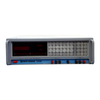
Illustrates and describes front panel controls and indicators.

3-3 REAR PANEL CONTROLS AND INDICATORS

3-4 MODES OF OPERATION

3-4 .1 TOTAL Mode

Explains TOTAL mode, SUM/AVG types, and measurement techniques.

3-4.3 IN PHASE Mode

Explains IN PHASE mode, vector components, and reference input needs.

3-4.7 RATIO R Modes

Describes RATIO R submodes: TOTAL, FUND, IN PHASE, QUAD.

3-10 SELF-CALIBRATION

3-10.1 Ten Frequency Self-Calibration Storage

Describes storing self-calibration data for ten frequencies.

3-10. 2 TOTAL (AVG) Calibration

Explains the self-calibration required for TOTAL (AVG) mode.

3-10.3 AUTOCAL Operation

Details the AUTOCAL function for automatic self-calibration.

3-12.1 AC Voltage Measurement

3-12. 2 Phase Sensitive AC Voltage Measurement

3-12.3 Phase Angle Measurement

3-12.4 Frequency Response Measurements in dB

3-12.5 THD Measurements

3-12.6 Percent Deviation Measurements

3-12.7 Harmonics Measurements

3-12.7.1 Harmonic Fundamental Amplitude

Guides on measuring the third harmonic amplitude.

3-12.7.2 Harmonic Inphase Component Amplitude

Details measuring the inphase component amplitude.

3-12.7.3 Harmonic Quadrature Component Amplitude

3-12.7.4 Harmonic Phase Angle Measurement

3-12.8 Transformation Ratio Measurement

3-12.11 Impedance Angle and Power Factor Measurements

3-12.12 Impedance Magnitude

3-12.13 AC Resistance and Reactance Measurements

SECTION 4 IEEE-488 STANDARD DIGITAL INTERFACE PROGRAMMING

4-1.2 Remote Program Language Selection

Explains selecting NATIVE, Model 225 EMULATION, or MATE-CIIL languages.

4-2 BUS COMMANDS

4-3 MODEL 2250 NATIVE LANGUAGE DEVICE DEPENDENT MESSAGES

4-3.1 Mode Progrannning

Details programming modes using function op codes and mnemonics.

4-3.1.2 Ratio R Mode Programming Examples

Gives examples of programming Ratio R modes.

4-3.2 Range Programming

4-3.2.1 Voltage Range Programming

Explains programming voltage ranges using SRX, VOLT, codes.

4-3.2.2 Ratio Range Programming

Details programming ratio ranges using SRX, RTIO, codes.

4-3.4 Measurement Modifier Programming

4-3.4.1 Harmonic Measurement Programming

Guides on selecting harmonics using SET, HARM.

4-3.5.1 Phase Offset Programming

Describes programming Phase Offset using SET, POFF.

4-3.5.2 Variable Scale Programming

Explains programming Variable Scale multipliers using SET, VARI.

4-3.5.6 dB Programming

4-4 MODEL 2250 NATIVE LANGUAGE TALK MESSAGES

4-5 MODEL 2250 NATIVE LANGUAGE SERIAL POLL

4-6.1 Assert SRQ With Stable Data or Measurement Timeout

4-7 MODEL 2250 NATIVE LANGUAGE GROUP EXECUTE TRIGGER REQUEST PROGRAMMING

SECTION 5 IEEE-488 MATE CONTROL INTERFACE INTERMEDIATE LANGUAGE OPTION

5-2.2 Format of FNC

5-3 PROGRAMMING APPLICATIONS (FNC)

5-3 .1 TOTAL Mode

Provides strings for TOTAL mode and voltage ranges.

5-3. 2 FUNDamental Mode

Gives strings for FUND mode and voltage ranges.

5-3.3 IN PHASE Mode

Provides strings for IN PHASE mode and voltage ranges.

5-3.4 QUADrature Mode

5-3.13 Reference Channel Measurements

SECTION 6 THEORY OF OPERATION

6-2. 2 Analog to Digital Converters

6-2.10 Input/Output CCA

Related product manuals