Do you have a question about the NORTHERN ELECTRIC BDM-2000 and is the answer not in the manual?
Defines the intended audience for the manual.
Details the requirements and skills for qualified personnel.
Defines end-users and their role in using the manual.
Explains the meaning of DANGER, WARNING, CAUTION, and NOTICE symbols.
Warns about electrical shock hazards from live components.
Warns about shock from live DC cables and components.
Highlights shock risks from over-voltages and lack of surge protection.
Warns about shock from ungrounded or live components during ground faults.
Warns about potential chemical exposure from damaged components.
Alerts to risks of fire or explosion under fault conditions.
Caution about property damage from unauthorized modifications.
Warns about burn hazards from hot product surfaces.
Alerts to injury risks from improper lifting or dropping.
Warns against connecting output to sources other than the utility grid.
Caution about using harsh chemicals for cleaning.
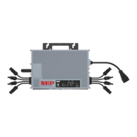
Identifies and labels various parts of the micro inverter.
Specifies the location of the product's serial number.
Explains the meaning of various symbols found on the product label.
Details critical safety warnings related to installation.
Discusses environmental pollution degrees affecting inverter performance.
Explains lightning risks and the importance of surge protection.
Emphasizes using components approved for wet locations.
Covers measuring service and installing the AC branch circuit junction box.
Details attaching the micro inverter to the racking system.
Explains connecting micro inverters into a branch circuit.
Highlights safety precautions for electrical connections.
Warns about the danger of electric shock from live components.
Guides on installing the AC branch circuit junction box.
Explains how to attach the product to the solar racking.
Provides critical spacing and placement advice for mounting.
Details connecting micro inverters into a branch circuit.
Warns about exceeding micro inverter limits per branch circuit.
Notes that NEP micro inverters are compatible with each other.
Reminds to apply protective end caps on unused connectors.
Provides an overview of safety instructions for DC connections.
Warns about electric shock from live DC cables and components.
Covers safety for DC cables, live components, load, PPE, and source disconnection.
Addresses shock risks from ground faults and cautions on DC input limits.
Covers PV module connector, polarity, switch, and mounting procedures.
Covers safety guidelines for disconnecting DC power and live components.
Covers qualified persons, voltage source disconnection, and initial steps like AC breaker.
Details verifying DC current/voltage, handling connectors, and disconnecting wires.
Covers AC connector disconnection, inverter removal, and bracket screw removal.
Step to attach replacement inverter to racking.
Step to connect AC cable to complete branch circuits.
Steps to complete connection map and connect PV modules.
Instruction to update PLC_ID in the BDG-256 gateway.
Covers utility approval, qualified personnel, and wiring integrity warnings.
Important notice regarding AP mode when AC is disconnected.
Information on finding the AP Number for WiFi setup.
Guide to connect to the device's WiFi hotspot.
Instructions to access the device's admin page via web browser.
Specifies that only 2.4GHz WiFi should be used.
Steps to configure the WiFi module with home network details.
Guide to select the home WiFi network.
Guide to enter the WiFi password.
Note that WiFi connects after plugging in AC.
Information about data upload timing to the cloud.
Guide to download the NEPViewer app from app stores.
Instructions for searching and downloading the app.
Instructions for logging in or registering an account for NEPViewer.
Guide to creating a new site within NEPViewer.
How to add gateways using the GATEWAY CODE.
Completing site details before proceeding.
Naming the site and filling in geolocation details.
Setting user preferences like temperature units and currency.
Confirmation message for successful site addition.
Confirmation message upon successful setup.
Details the meaning of LED indicators for different statuses.
Lists various error codes and their corresponding meanings.
Warning against attempting self-repair of the micro inverter.
Covers warnings for DC connector disconnection, reconnection, and AC power disconnection.
Guides on checking utility connection, power, AC harness, and AC disconnects.
Covers verifying DC voltage, connections, and PLC signal quality.
Recommendation to install LCF to block interference.
Final step to call customer support if issues persist.
Warning against attempting self-repair of the micro inverter.
Instructions for disposing of the product according to WEEE regulations.
Guidance on packing the product for storage or shipping.
Instructions for disposing of or replacing the product.
Presents DC input specifications for the inverter.
Details AC output specifications for the inverter.
Provides information on the inverter's peak and MPPT efficiency.
| Input Voltage | 12V DC |
|---|---|
| Frequency | 60 Hz |
| Category | Inverter |
| Continuous Power | 2000 Watts |
| Peak Power | 4000 Watts |
| Efficiency | 90% |
| Protection Features | Overload, Short Circuit, Over Temperature, Low Voltage, High Voltage |