34
RE1: Not used.
RE2: Gator Mode
Displayed as: GtMode
Initial value: Mono16
Range of adjustment: see table at page 44
The Mode parameter allows you to select one of 6 methods of combining the two sets of
four note Groups, {A} and {B}. Three of the modes are mono, and three are stereo, in which
notes in Set {A} are routed to the Left output and those in Set {B} to the Right output.
The Pan controls on FX Menu Page 1 will override the stereo Gator Modes. The
stereo modes will only operate as described if the main FX Pan controls are set
centrally.
RE3 and RE4: Select Edit Group
Displayed as: EditGroup
Initial value: 1
Range of adjustment: 1 to 8
The pattern editor lets you adjust the steps in the sequence in groups of four, called Edit
Groups. Edit Groups 1 to 4 constitute the top row of the pattern display, Set {A}, and
hence the first 16 steps of the pattern. Edit Groups 5 to 8 constitute the bottom row of
the pattern display, Set {B}, and hence the second 16 steps of the pattern (except when
Mono16 Mode is selected, the pattern then consisting only of the first 16 steps). Either
RE3 or RE4 may be used to select Edit Groups. A set of four letter “E’s” is displayed in the
central area of the LCD, and these change position as RE3/RE4 is moved, to indicate the
step positions of the sequence that are selected for editing.
RE5 to RE8: Step Editors
The four remaining rotary encoders control which individual steps will be present in the
Gator pattern. The pattern to be played is represented by the 32 ‘solid’ characters to the
right of the LCD. When Edit Group 1 is selected (by RE3/RE4), RE5 will select Step 1,
RE6 Step 2, RE7 Step 3 and RE8 Step 4. When Edit Group 2 is selected, RE5 will select
Step 5, RE6 Step 6, and so on. The rotary encoders do not only select whether a particular
step is part of the sequence, they also set the volume of the step. Seven different levels are
possible, plus ‘off’ – i.e., the Step not being played at all. The height of the ‘solid’ character
indicates the step’s volume.
the vocoDer
A Vocoder is a device which analyzes selected frequencies present in an audio signal
(called a Modulator), and superimposes these frequencies onto another sound (called the
Carrier). It does this by feeding the Modulator signal into a bank of band pass filters. Each
of these filters (12 of them on the UltraNova) covers a particular band in the audio spec-
trum, and the filter bank thus “splits” the audio signal into 12 separate frequency bands.
The result of this arrangement is that the spectral content – i.e. the “character” of the audio
signal is “imposed” upon the synth sound, and what you hear is a synth sound simulating
the audio input (typically a vocal).
The final character of the vocoded sound will depend greatly on the harmonics present
in the synth sound used as the Carrier. Patches very rich in harmonics (for example using
Sawtooth Waves) will generally give the best results.
Typically, the Modulator signal used by a Vocoder would be a human voice speaking or
singing into a microphone. This creates the distinctive robotic or ‘talky’ like sounds which
have recently returned to popularity and are now being used in lots of current music
genres. Bear in mind however, that the Modulator signal need not be restricted to human
speech. Other types of Modulator signal can be used (for example, an electric guitar or
drums) and can often give quite unexpected and interesting results.
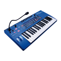
The most common way of using the Vocoder is with the dynmaic gooseneck mic supplied
with the UltraNova (or any other dynamic mic) plugged into the top panel XLR socket.
Alternatively, the Modulator signals may be from an instrument or other source connected
to the AUDIO IN sockets [11] & [12], located on the rear panel, but remember that a jack
plug connected at Input 1 will override the top panel XLR input. The Modulator input to the
Vocoder is always mono, so a stereo source connected to Inputs 1 and 2 will be summed.
The pitch of the final vocoded sound will depend on the notes that the Carrier (the cur-
rently selected Patch) is playing. Notes can either be played on the UltraNova’s keyboard
or received via MIDI from an external keyboard or sequencer. Both Carrier and Modulator
signals must be present simultaneously for the Vocoder effect to work, so notes must be
played while the Modulator signal is present.
The Vocoder is enabled and controlled by pressing the VOCODER button [19], which
opens the Vocoder Menu.
RE1: Vocoder On/Off
Displayed as: On/Off
Init value: Off (On now for audition)
Range of adjustment: Off or On
Enables/disables the Vocoder function. When set to Off, the vocoder may be configured
and auditioned as long as the Vocoder Menu is displayed. Vocoder action will stop if
another Menu is opened. Once the Vocoder has been set On, it will remain operational
with any Menu open.
RE2 & RE3: Not used.
RE4: Vocoder Balance
Displayed as: Balance
Init value: v63 m0
Range of adjustment: v0 c64 to v63 c1; v63 m0 to v0 m63
Characteristic Vocoder sounds are obtained by blending the Vocoder output with one or
other of the two source signals. This parameter lets you mix the output of the vocoder (v)
with either the Modulator signal (m) or the Carrier signal (c). Rotating the encoder clock-
wise, you will see that the first half of the value range comprises combinations of Vocoder
and Carrier – “v0 c64” means only Carrier signal and no Vocoder effect at all, “v32 c32”
means that Vocoder output and Carrier signal are mixed in equal proportions. The second
half of the value range performs the same mixing principle of Vocoder output and Modulator
signal.
RE5: Vocoder Width
Displayed as: Width
Init value: 127
Range of adjustment: 0 to 127
The outputs of each Vocoder filter band are routed to the Left and Right channels alter-
nately to produce a stereo image with good depth. Decreasing the value of Width will
progressively route all the filter outputs to both outputs, so with Width set to zero, the
Vocoder output will be in mono and centrally located in the stereo image.
RE6: Vocoder Sibilance Level
Displayed as: SibLevel
Init value: 40
Range of adjustment: 0 to 127
Determines the amount sibilance that will be present in the final vocoded signal, and can
make the Vocoder emphasise the explosive ‘S’ and ‘T’ sounds found in speech. Sibilance
can be added to give the Vocoder to give a more distinctive sound and to make vocoded
vocals more intelligible.
RE7: Vocoder Sibilance Type
Displayed as: SibType
Init value: HighPass
Range of adjustment: High Pass or Noise
In the default setting of HiPass, sibilance is extracted from the Modulator signal (i.e. the
vocalist’s natural voice) by filtering. This setting will allow some of the Modulator signal
to be heard. If you want to add some sibilance to the vocoded vocals, but the performer’s
voice just isn’t that sibilant naturally, you can artifically simulate sibilance by selecting Noise
as Sibilance Type. This will add a small level of noise to the Modulator signal and the voc-
oder will treat the additional HF content in the same manner as it would natural sibilance.
RE8: Not used.
 Loading...

