Chapter2 Connection
Manual of NCH02
- 10 -
As the Figure 2-2 showed, Marked No. 3 position is the limited /home input port. they are
the optical isolated Input interface. The input interface is a 11P 3.81 direct insertion terminal
interface, as shown in Figure 2-2 shell silk print, and definition is
GND/INP1/INP2/GND/INP3/INP4/INP5/INP6/INP7/INP8/12V from left to right. Internal
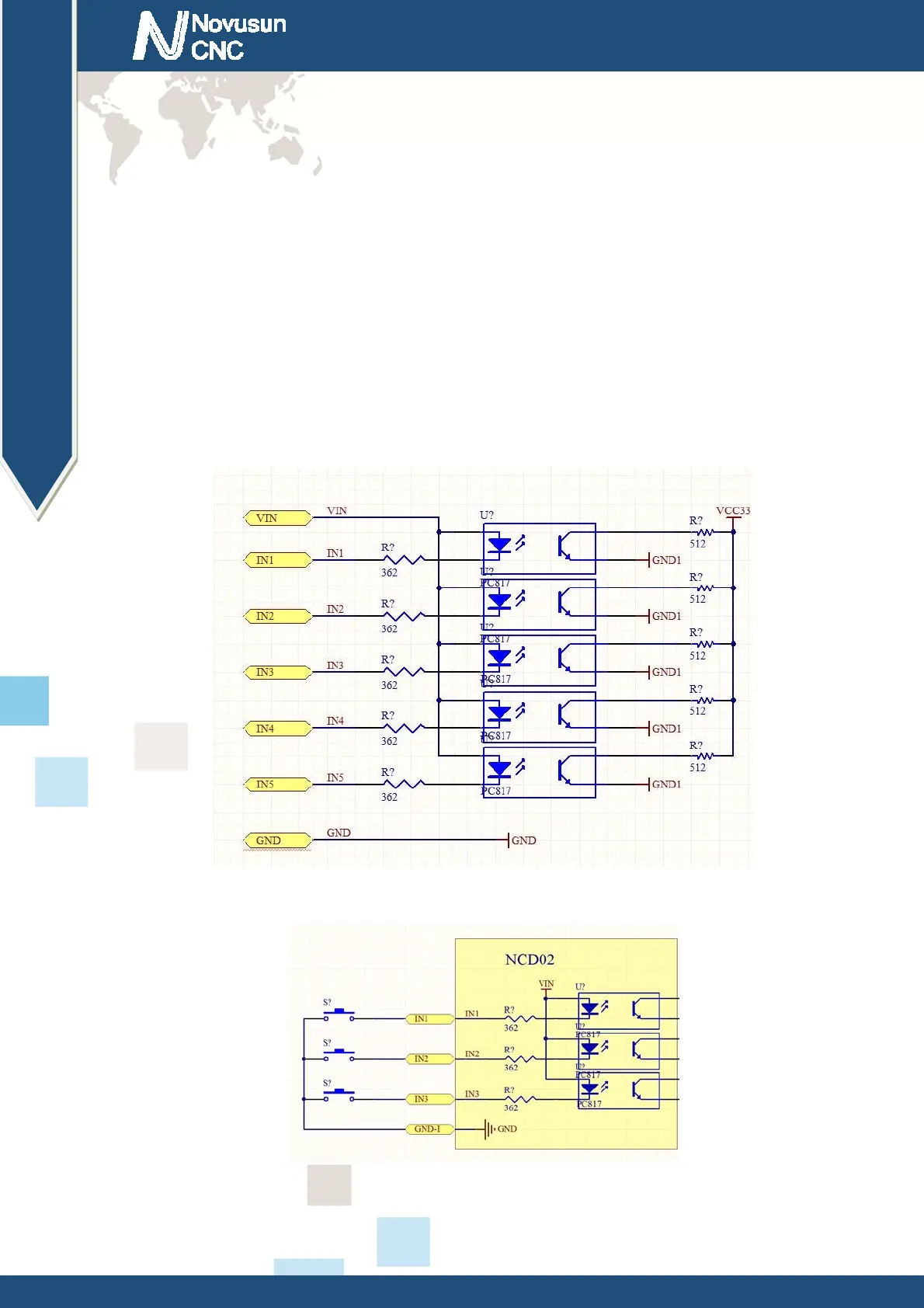
structure reference figure 2-3. The interface is a common negative interface, which can be
connected with a micro switch, a 2 line proximity switch or a NPN type 3 line proximity switch.
The interface is isolated by the optocoupler, and the internal structure diagram is referred to
figure 2-4. Estop, micro switch, 2 line proximity switch connection method reference figure 2-5.
Figure2-3. Internal structure diagram of the input port
Figure2-4. Probe/Estop/ ordinary fretting switch input connection
www.nvcnc.net
 Loading...