NL 4 INSTALLATIE
1
Voorbereiding montage: Teken op de muur de verticale
aslijn A van de schouwkap. De advieshoogte “h” tussen
de onderkant van de schouwkap en de kookplaat is
voor
• Advies montagehoogte met elektrische of keramische
kookplaat (Hmin-Hmax) (mm): 600 - 750
• Montagehoogte met gas of inductie kookplaat
(Hmin-Hmax) (mm): 650-750
De waterpaslijn B wordt getekend op de gekozen
hoogte van “h” + 440 mm.
Plaats het stopcontact dichtbij de verticale aslijn A
binnen de breedte van de schouwen en boven het
motorhuis en onder de recirculatiebox (M).
2 3
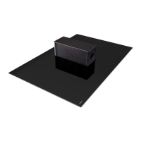
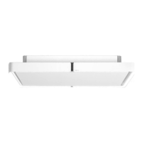
Positioneer de montageplaat (M) van de recirculatiebox
in het midden van de verticale aslijn en tegen het
plafond. In geval van een stenen muur markeer en boor
de 3 gaten (Ø8mm). Gebruik de pluggen (3x 906.055)
en schroeven (3x 906.143) om de montageplaat (M) te
installeren. In geval van een houten bevestigingsmuur
de spaanplaatschroeven (3x 906.192) gebruiken.
4 5
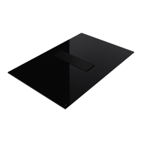
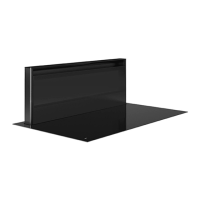
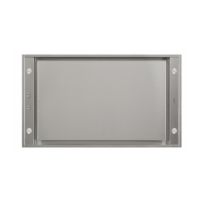
Positioneer de recirculatiebox (H) op de montageplaat
(M). Let op bij het plaatsen van de recirculatiebox dat
deze niet vervormd of opengevouwen wordt tijdens
montage.
1.
Laat H steunen op de uitstekende lip van M.
2. Kantel H naar het muurbeugel M toe.
3. Haak de lip van H achter de muurbeugel M.
DE 4 INSTALLATION
1
Vorbereitung der Montage: Zeichnen Sie auf der
Wand die vertikale Achsenlinie A der Wandhaube an.
Die empfohlene Höhe „h“ zwischen Unterseite der
Wandhaube und der Kochfläche beträgt für
• Die empfohlene Montagehöhe bei einem Elektrrooder
Keramikkochfeld beträgt mindestens 600 mm und
höchstens 750 mm.
• Die empfohlene Montagehöhe bei einem Gasoder
Induktionskochfeld beträgt mindestens 650 mm und
höchstens 750 mm.
Die
horizontale Linie B wird auf der gewählten Höhe
von „h“ + 440 mm gezeichnet.
Positionier
en Sie die Steckdose nahe der vertikalen
Achsenlinie A innerhalb der Breite der Schächte und
über dem Motorgehäuse und unter der Umluftbox (M).
2 3
Halten Sie die Montageplatte (M) der Umluftbox gegen
die Decke und positionieren Sie sie in der Mitte der
vertikalen Achsenlinie. Im Fall einer Steinwand zeichnen
Sie die 3 Löcher an und bohren Sie sie (Ø 8 mm).
Stecken Sie die Dübel (3x 906-055) und die Schrauben
(3x 906-143) in die Löcher, um die Montageplatte (M)
zu installieren. Im Fall einer Befestigungswand aus
Holz verwenden Sie die Spanplattenschrauben (3x
906-192).
4 5
Positionieren Sie die Umluftbox (H) auf der Montageplatte
(M). Achten Sie beim Positionieren der Umluftbox
darauf, dass sie während der Montage nicht verformt
oder geknickt wird.
1. Setzen Sie
H auf die hervorstehende Kante von M
auf (siehe
5
).
2. Kippen Sie H zum W
andbügel M hin.
3.
Haken Sie die Kante von H hinter den Wandbügel M.
FR 4 INSTALLATION
1
Préparation du montage : Tracez sur le mur l’axe
vertical A de la hotte à cheminée. La hauteur « h »
conseillée entre le bas de la hotte à cheminée et la
table de cuisson est
• La hauteur de montage recommandée avec une
table de cuisson électrique ou céramique est de
600 mm minimum et 750 mm maximum.
• La
hauteur de montage avec une table de cuisson
au gaz ou à induction est de 650 mm minimum et
750 mm maximum.
La ligne horizontale B sera tracée à la hauteur
« h » choisie + 440 mm.
Placez la prise de courant près de l’axe vertical A
l’intérieur de la largeur des gaines, au-dessus du
boîtier du moteur et sous la boîte de recirculation (M).
2 3
Positionnez la plaque de montage (M) de la boîte
de recirculation au milieu de l’axe vertical et contre
le plafond. Dans le cas d’un mur en pierre, marquez
et percez 3 trous (Ø 8mm). Utiliser les chevilles (3x
906-055) et les vis (3x 906-143) pour installer la plaque
de montage (M). Dans le cas d’un mur de fixation en
bois, utilisez des vis pour panneaux en aggloméré (3x
906-192).
4 5
Positionnez la boîte de recirculation (H) sur la plaque
de montage (M). Lors de la mise en place de la boîte
de recirculation, assurez-vous qu’elle ne se déforme
pas ou ne se déplie pas pendant le montage.
1. Faites en sorte que H soit soutenue par la patte
saillante de M (voir
5
).
2. Basculez H vers l’étrier mural M.
3. Accrochez la patte de H derrière l’étrier mural M.
EN 4 INSTALLATION
1
Preparations for mounting: Draw the vertical axis A
of the chimney hood on the wall. The recommended
height ‘h’ between the bottom of the chimney hood
and the cooking plate is for
• The recommended mounting height for an electrical
or ceramic cooking plate is min. 600 mm and max.
750 mm.
• The mounting height for a gas or induction cooking
plate is min. 650 mm and max. 750 mm.
The level line B is drawn at the chosen height of
‘h’ + 440 mm.
Position the socket outlet near the vertical axis A within
the width of the shafts and above the motor housing
and below the recirculation box (M).
2 3
Position the mounting plate (M) of the recirculation
box in the middle of the vertical axis and against the
ceiling. In case of a stone wall, mark and drill the 3
holes (Ø 8 mm). Install the mounting plate (M) using
the plugs (3x 906-055) and screws (3x 906-143). In
case of a wooden mounting wall, use the chipboard
screws (3 x 906-192).
4 5
Position the recirculation box (H) on the mounting plate
(M). Make sure when positioning the recirculation box
that it is not deformed or unfolded when mounting.
1. Let H rest on the protruding lip of M (see
5
).
2. Tilt H towards the wall bracket M.
3. Hook the lip of H behind the wall bracket M.
7
 Loading...