MODEL#:
TU40
FEATURES:
• Rea l -Ti me Cl o c k Fa c e w i th
OFF/ AUTO/ ON Override Switch
•
Captive Trippers
• 15 Minute Intervals
• NEMA 3R Plastic Indoor/ Outdoor
Enc l o sur e
•
Green LED Indicates power
• Red LED indicates load status
•
40 AMP DPDT Contacts
• 8-18 AWG Screw Terminals
OUTPUT:
DPDT, Dry Contacts (Unpowered) all in one may also be used for SPST, SPDT, DPST
CONTACT RATINGS: NO CONTACTS:
40 AMPS RESISTIVE @ 120-277 VAC 60Hz
30 AMPS INDUCTIVE @ 120-277 VAC
1HP, 30FLA, 90LRA @ 120 VAC
2HP, 20FLA, 60 LRA @ 240 VAC
30 AMPS BALLAST @ 120 VAC
20 AMPS BALLAST @ 277 VAC
15 AMPS TUNGSTEN @ 120 VAC
20 AM PS RESISTIVE @ 2 8 VDC
720 VA PILOT DUTY @ 120-240 VAC
30 AMPS MAX ABOVE 104°F
NC CONTACTS:
30 AMPS RESISTIVE @ 120-277 VAC 60Hz
15 AMPS INDUCTIVE @ 120-277 VAC
1/ 4HP, 12FLA, 30 LRA @ 120 VAC
1/ 2HP, 12FLA, 33 LRA @ 250 VAC
10 AMPS BALLAST @ 120-277 VAC
290 VA PILOT DUTY @ 120VAC
360 VA PILOT DUTY @ 240 VAC
OPERATING TEMP:
-31°F to 116°F (-35°C to +47°C) Relative Humidity is 10% to 95%
TIM ER SUPPLY:
120/ 208-240/ 277VAC, 60Hz Detects voltage automatically (NO DIP SWITCH SETTING REQUIRED)
POW ER CON SUMPTION:
6VA Max @ 120VAC
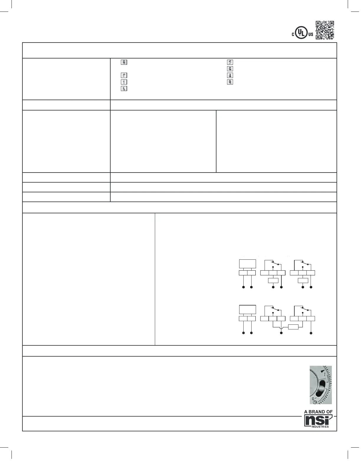
INSTALLATION & WIRING DIAGRAMS
UNIT IS TO BE INSTALLED BY A
LICEN SED ELECTRI CIA N
1. Mount the enclosure at eye level using screws or
other suitable fastening device. Bring supply and
load wires in through bottom or side knockouts.
2. Wire as per typical wiring diagram below, and
follow all local and NEC codes.
3. To ensure proper connection to the terminal
block, turn the screw fully counterclockwise
before inserting wires. Firmly fasten the screw
terminal
SETTIN G ON/ OFF TIM ES
1. The timer has 96 tabs which can turn loads ON or OFF every 15 minutes. Push tabs outward to turn the load ON,
and pull them inwards to turn the load OFF for the desired ON and OFF durations.
2 . Rotate di a l clockw i se to set the ti me. A li gn ti me w i th arrow. DO N O T ATTEM PT TO SET THE TIM E BY USIN G
THE M IN UTE HA N D IN THE CEN TER O F THE DIAL.
3. Automatic operation: To execute the programmed schedule, set the selector switch to the center position.
(Shown by clock symbol)
4. MANUAL OVERRIDE: Set the switch to the “ I” position to turn the load permanently ON.
Set the switch to the “0” position to turn the load permanently OFF.
877.230.7874 • www.nsiindustries.com
UNIVERSAL MULTI-VOLTAGE
ELECTRO M ECHA N I CA L TIM E SW ITCH
Use copper wire AWG 8-18 suitable for 90°C. WIRING TO COMPLY WITH ALL LOCAL AND NA-
TIONAL ELECTRICAL CODES. Bonding between conduit connection is not automatic and must
be provided as part of the installation. THE ENCLOSURE MUST BE PROPERLY GROUNDED.
Minimum 10.6 lb. in. torque required at the terminals to ensure proper connections. Strip the
supply and load wires to 1/ 2” .
LI-831( C)
PATENT PENDING
N
LN
NCNOC
LN
NCNOC
LN
Typical Wiring Diagram, 120 VAC Appl i cat i on
HN
L1 L2
NCNOC
L1
NCNOC
L2
TIMER
SUPPLY
TIMER
SUPPLY
LOAD LOAD
LOAD
H
Typical Wiring Diagram, 208-240 VAC Applicat ion
Typical Wiring Diagram, 120/ 277VAC Appl icat ion
 Loading...