8. More Advanced Function
— 8-30 —
8.5.4. Automatic Gain Switching
Automatic gain switching function is to change over the servo gain for operation to the servo gain for
stopping, depending on the position deviation.
The parameters PG and VG (gains for operation), and the PGL and VGL (gains for stopping) are used to
switch the servo gain. There are two use examples as follow depending on tuned condition.
1) For control of vibration at stopping by lowering the gain when the gain for operation cannot be
increased because of low dynamic rigidity of the work attached to the Motor.
2) Set lower gain for operation and higher gain for stopping to control vibration when operating
and for short settling time when stopping
Table 8-31: Parameter related to gain switching function
0: Switch gain off.
1 to 2 621 439
Position loop proportional gain
Velocity loop proportional gain
Position loop proportional gain for stopping
Velocity loop proportional gain for stopping
Monitor of gain switching state
0: Stopping gain (PGL and VGL)
1: Gain for operation (PG and VG)
The gain switching function is not available when the parameter GP is set to GP0. In such case, the
parameters for operation PG and VG is always effective.
If setting of the parameter GP is other than 0, the gains PG and VG are used for operating the Motor.
When the Motor stopped and the position error falls below the setting of parameter GP, the gains PGL and
VGL for stopping are used.
If the parameter GT (Switching gain timer) is set, the gain will be switched to the stopping gain after
confirming that the position error stays below the setting of GP longer than a time set by the GT.
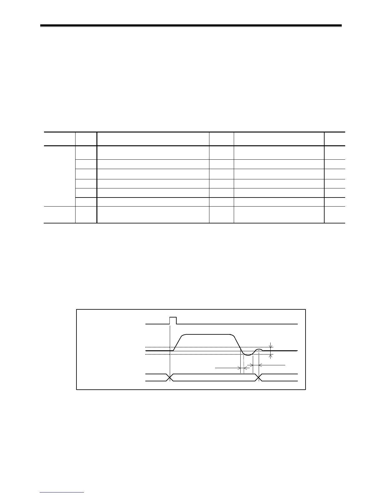
Fig 8-13: Functioning timing of gain switching
Stability timer
Example: GT5: 5 ms
RS-232C command or
RUN input
The gains PG and VG are forcibly used when the internal pulses are being generated for the
program positioning or the RS-232C command positioning; or when the pulse train command is
being inputted.
In case of a positioning with external pulse train command, the System regards it as no pulse
input if the inputting pulse frequency falls under 10 [kpps], thus causing frequent gain
switching. In such a case, setting the parameter GT controls frequent gain switching.
 Loading...