4 5
Fig. 3
Water Tube
Water Filter Case
Connector for Water
Fig. 2
Cover
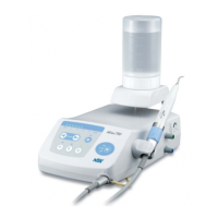
1) Remove the Dust Cover from the Bottle Base. (Fig. 5)
2) Remove the cap of the Irrigation Bottle and fill solution to
the desired level.
3) Close the cap of the Irrigation Bottle, check the Air Hole
is clean and insert the Joint into the Bottle Base
Connector until it clicks into place. (Fig. 6)
Use of BottleUse of Bottle
Fig. 5
Fig. 6
Make sure the connector and surrounding area
is completely clean before installing the Irrigation
Bottle. Wipe the Irrigation Bottle and Connector
Area thoroughly prior to inserting the Irrigation
Bottle.
CAUTION
Dust CoverDust Cover
Air HoleAir Hole
Bottle BaseBottle Base
Joint Hole
Joint
Fig. 7
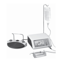
(1) Water System Setup
1) Remove the Cover from the Connector for Water. (Fig. 2)
2) Connect the filter side of the Water Tube deep into the
water connector on the Varios Control Unit. (Fig. 3)
3) Connect the provided water tube to the water outlet on
the dental unit.
3. Prior to Operating System
Use of City WaterUse of City Water
· Insert the Water Tube deep into the connector on
the Control Unit.
· If water has not been used at the water outlet of
the dental unit for a long time, brownish water
may come out but wait until clean water comes
out. Then connect it.
CAUTION
Fig. 4
NOTICE
· Pushing the White Ring, (the Quick Connector
Release Ring) on the Water Connector, gently
remove the Tube. (Fig. 4)
· When the water tube is not connected, mount
the cover on the connector on the Control Unit.
NOTICE
· To remove the bottle, pull up the bottle gently.
· The Irrigation Bottle graduations are printed on both
sides of the bottle and can be read accurately from
the fill position or mounted on the Control Unit.
· Mount the Dust Cover when not in use.
White Ring
Push
Push
(2) Foot Control Connection
Connect the Foot Control Plug to the Foot Control Connector
at the back of the Control Unit, take care in properly align all
the pins. Push the Plug gently into the Connector. (Fig. 7)
Fig. 8
Fig. 9
Fig. 10
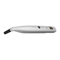
1) Align the Marks on the Handpiece Plug and the Control Unit. Gently insert.
2) Loosen and remove the Cap. (Fig. 9)
3) Insert firmly the Irrigation Tube deep into the Connector. (Fig. 10)
Align the Marks on the Control Unit and the Handpiece Plug. Gently push the Plug into the Connector. (Fig. 8)
(3) Handpiece Connection
(4) Mounting Power Cord
Insert the Power Cord into the Inlet at the back of the Control
Unit. (Fig. 11)
Use of City WaterUse of City Water
Use of BottleUse of Bottle
Mount the Cap when the Irrigation Tube is not
connected.
NOTICE
Fig. 11
Power Cord
Inlet
Mark
Handpiece Cord
Connector
Handpiece Plug
CapCap
Irrigation TubeIrrigation Tube
ConnectorConnector
Foot Control ConnectorFoot Control Connector
MarkMark
Foot Control Plug
Foot Control Plug
 Loading...