6 7
Fig. 15
Power SwitchPower Switch
Front PanelFront Panel
Fig. 12
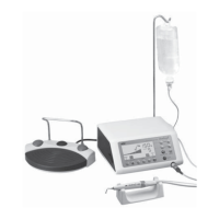
Picture shows Varios 750 LUX
Fig. 13
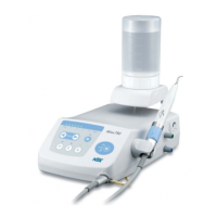
Picture shows Varios 750 LUX
Fig. 14
Picture shows Varios 750 LUX
Mount the Tip by fastening it lightly by hand. (Fig. 12)
Insert the Tip through the hole of the Tip Wrench, align the four cornered tip's base into the hole of the Tip Wrench. Turn it
clockwise until the wrench clicks. (Fig. 13)
To remove the Tip, turn counterclockwise with the Tip Wrench.
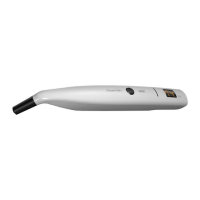
4. Mounting and Removing Tip
When mounting the handpiece, align the positioning Marks
on the handpiece and the Handpiece Cord. Push straight
inmost.
When removing the handpiece, grip the Front and the Rear
of the handpiece firmly. Pull to separate. (Fig. 14)
5. Mounting and Removing the Handpiece
· Detach Tip before removing handpiece.
· Push handpiece against handpiece plug inmost to connect.
· When removing the handpiece, grip the plug of the Handpiece Cord.
CAUTION
· When mounting the tip, always use groves, tip wrench. Handpiece that have been sterilized.
· Tip Wrench is consumable For reliable operation replace annually.
CAUTION
Do not touch the handpiece backend. (where
Electrical Connections are made to the cord.)
It might result in electrical shock.
WARNING
(1) Water System Setup
Carefully check all water supply connections prior to starting procedure.
Open the dental unit's water valve.
Set water pressure between 0.1~0.5MPa (1~5 kgf/cm
2
).
Check that the Bottle is filled to the proper level.
6. Operating Procedures
Use of City WaterUse of City Water
Use of BottleUse of Bottle
Tip
Tip WrenchTip Wrench
Tighten
Tighten
Tighten
Tighten
Loosen
Loosen
Loosen
Loosen
Mark
Mark MarkMark
JointJoint
HandpieceHandpiece Handpiece PlugHandpiece Plug
Fig. 16Tip Case Label
Set to
P
Set to
E
Set to
G
Mode Selection Key
Fig. 17
(3) Power Range Setting
Check the case the selected Tip came in for proper power.
You can check Maximum Power on the Tip Case Label. Check
your model.
1) Select the Operating Mode with the Mode Selection Keys on the Front Panel. The light over the selected mode will
illuminate. (Fig. 17)
(2) Power On
Connect the Power Cord to the wall outlet.
Turn on the Power Switch of the Control Unit.
Front Panel will light up.
Power Level Key
Decrease
Increase
Power Display Panel
Fig. 18
2) Set the power level with the Power Level Key on the
Front Panel. The lamps in the Power Display Panel will
indicate the selected power level. Make sure the
power level is set in the appropriate range for the
selected Tip. (Fig. 18)
Do not exceed Muximun power level for the Tip. It could damage teeth plane and the Tip could be broken.
CAUTION
· Continuous pushing of the Power Level Key will cause the Power Level Display to climb.
· When only water is desired without oscillating the Tip, keep pressing “Decrease” key to extinguish Power Display
Pannel Lamp.
NOTICE
POWER RANGE
Low High
Model
Maximum Power
 Loading...