21Page 9
QUICK GUIDECommission an Installed Sound Environment
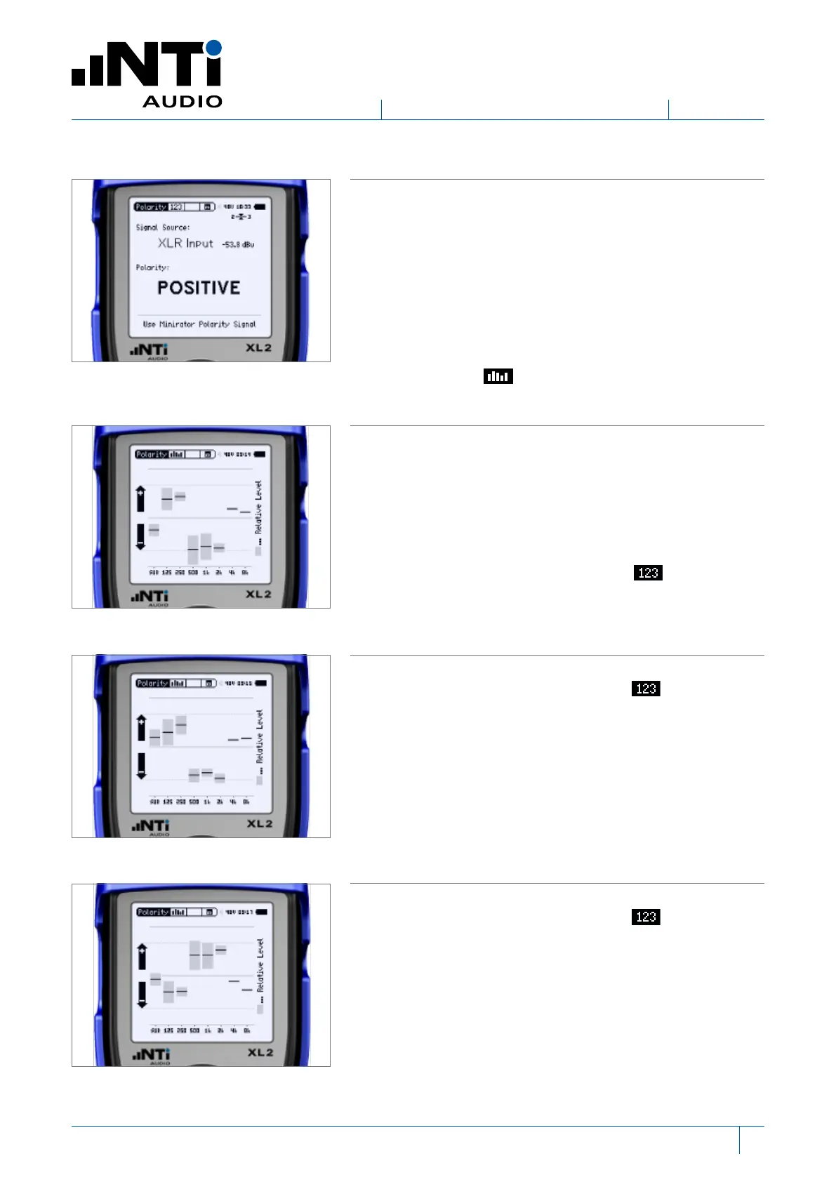
The overall polarity of the speaker is shown.
This overall polarity result obtained may vary between speak-
ers even if the speakers are wired the same. This is due to
reflections from the speaker ports and/or nearby surfaces
and/or the non-exact placement of the microphone. Further,
speakers in multi-speaker cabinets often have mixed po-
larities by design. We therefore look at the polarity in more
detail by examining 8 octave bands.
On the XL2, select from the second menu.
The polarity spectrum shows individual phase information
for different frequency bands. The position of the center of
each band indicates the polarity of the band while the length
of the band represents how much energy is being received
in that band.
For Speaker 1, as most energy is in the lower half of the
screen, the overall polarity shown on the screen is neg-
ative.
For Speaker 2, as most energy is in the upper half of the
screen, the overall polarity shown on the screen is posi-
tive.
However, as the pattern of the frequency bands are similar
(in so much as inverting the pattern over the center horizon-
tal line would create a pattern that was less similar), we can
conclude that Speakers 1 and 2 have the same polarity.
For Speaker 3, as most energy is in the upper half of the
screen, the overall polarity shown on the screen is posi-
tive.
However, as the pattern of the frequency bands is similar
when inverted, we can conclude that Speaker 3 has a dif-
ferent polarity to both Speakers 1 and 2.
Speaker 1
Speaker 2
Speaker 3
www.nti-audio.com
 Loading...


