2
nuaire.co.uk 029 2085 8400 12. 12. 17. Leaflet Number 671432
Installation and Maintenance
ES-ISC Ecosmart Speed Control
3.1 Mechanical Installation
For ease of installation, remove the front cover and disconnect any
cooling fans fitted. Remove the control casing from the base, offer the
base to the wall (or mark from the drill pattern).
Drill and fix the base to the wall using appropriate fasteners. It may be
easier to connect the field wiring at this stage. Reassemble the case
ensuring that cooling fans are reconnected.
IMPORTANT
The operating range is 0°C to 35°C, up to 85% relative humidity
(non-condensing).
Installation in unventilated loft is not recommended.
IMPORTANT
Isolation - Ensure that the unit is electrically isolated from the mains
supply before commencing work.
Motors of 4kW and above must be connected to Delta ∆
The screening of the power cable must be continuous. Bridge any
breaks (e.g. at local isolators) using braided earthing cable. Ensure the
screening is earthed at both ends.
IMPORTANT
To minimise the possibility of Electro Magnetic interference:
•Always install screened cable between the control and the fan,
maximum length 30 metres. Consult Nuaire if a longer cable run is
needed.
•This product must be earthed and always ‘earth’ the screened cable
at both ends. Ensure that ALL earth connections are the same
potential. Cable glands are provided.
•Always keep mains supply cables and motor supply cables separate
and DO NOT install any data cable or low voltage cable in the same
containment as mains carrying cables.
3.2 Electrical
The mains power supply to the controller must be appropriately sized
and installed via a local isolation switch (by others). The isolator must
also accommodate the 230V switched live (if used).
The mains supply from the Ecosmart controller to the fan must be
appropriately sized, not exceeding 30 Metres and must be a screened
power cable, earthed at both ends. A four point glanding plate is
formed from the base of the control and in order to maintain EMC
compliance, an EMC glanding kit is supplied.
Ecosmart controls and sensors are supplied with 10 metres of data
cable plugged at both ends, if used these can now be fitted and plugged
in to the low voltage sockets on the Ecosmart control board.All other
low voltage connections i.e. BMS can also be completed.
N
L
SL
Remove this link wire if:
1. A switched live signal is connected.
2. An ES-PIR, ES-LCD or BMS signal is connected.
Max SL run on Min
Trickle Test
10
Pwr
Standby
Fan 1
Fan 2
Heating
Cooling
Fault
Frost
Tx
Rx
Ecosmart
Earth
FAULT RUN
DAMPER
E L3L2 N L1
E N L1 L2 L3
Mains supply connections
400V 50Hz 3ph + Neutral
via local isolator.
1 5 3
2 4 6
(U) (V) (W)
CONTACTER
A1
A2
0V
0-10V
BMS signal
'NET' connection
U V W E
DP
CL
Connections to fan via screened
power cable. Purpose made glands
are provided to earth the screening.
N
RET
Note: Internal connections
between the supply terminals,
output contactors, the PCB and
inverter are made at the factory
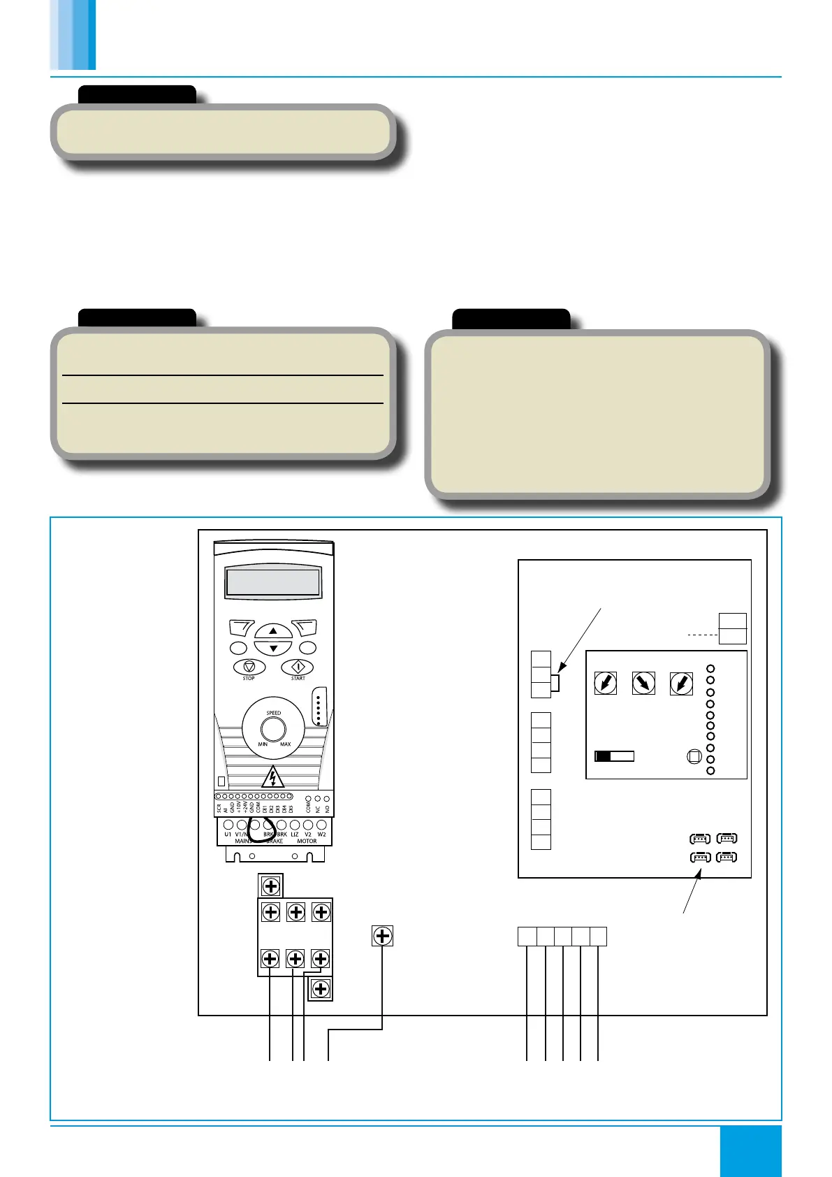
Figure 4. ES-ISC wiring
diagram.
 Loading...