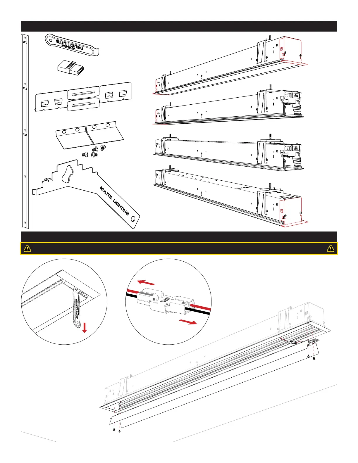
If access to wire way is needed, remove the four screws from
the LED refl ector. To remove the refl ector completely, separate
the electrical disconnect. Store the refl ector in a clean, safe
place during installation or maintenance.
2
OVERVIEW
MAINTENANCE
ALIGNMENT TABS
(BREAK INTO FOUR PIECES)
*NOTE: JOINT
COVER BRACKET
MAY BE DIFFERENT
THAN SHOWN.
JOINT COVER BRACKETS AND
HARDWARE (4) 8-32 X 1/4”
PHILLIPS PAN HEAD SCREWS
RECESSED
JOINING TOOL
HOLE CUTTING TEMPLET TOOL
(NOT TO SCALE)
LENS REMOVAL TOOL
INTERMEDIATE POWER
SUPPLY COUPLER
END LUMINAIRE
RIGHT END CAP
STARTER LUMINAIRE
LEFT END CAP
STAND ALONE
LUMINAIRE END
CAPS AT EACH END
MID LUMINAIRE
NO END CAPS
Gently insert lens removal tool at one end
of the lens and pull down. Pull the exposed
end down and remove lens. Store the tool in
a safe place.
AVOID TOUCHING THE LED BOARDS.
 Loading...