BOLD ratings are factory wired. See "OPTIONAL WIR-
ING CONVERSION" section for wattage and voltage
conversion instructions.
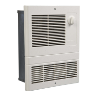
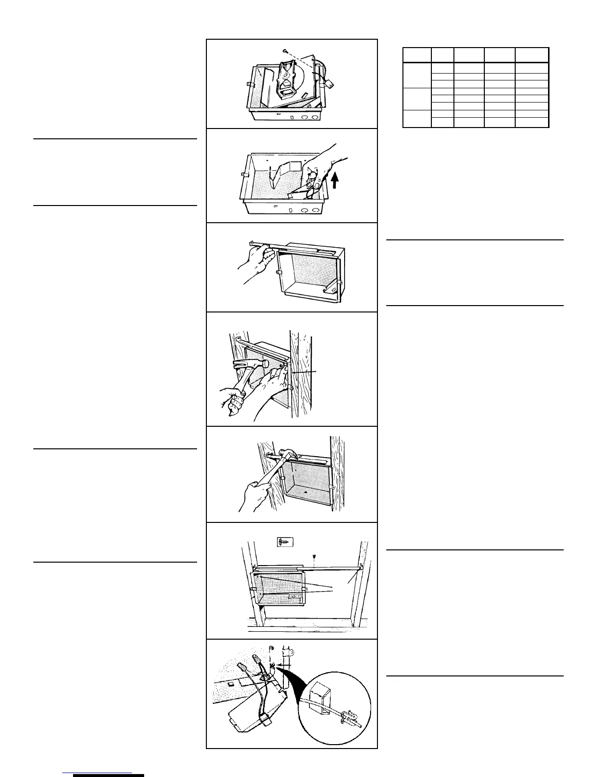
Follow these basic steps when installing this heater.
• Nail housing to studs.
• Connect power cable.
• Fasten heater assembly and grille to
housing. (FIG. 1)
PREPARE
THE HOUSING
1. Remove the retaining screw, unplug wiring har-
ness and lift heater assembly from housing. (FIG. 2)
2. Slide the wiring cover out of housing. (FIG. 3)
INSTALL
THE HEATER
(16"-ON-CENTER STUDS ONLY)
NOTE: Locate housing at least 6" from the floor and
any adjacent walls.
1. Choose which side of housing will be mounted
directly to a wall stud. Then insert a mounting
bracket
from the opposite side into the channel
at the top of the housing. (FIG. 4)
2. Use measuring guide on side of housing to posi-
tion housing so that it will be flush with finished
wall. Drive to (2) nails through the holes on side
of housing and into stud. (FIG. 5)
3. Extend mounting bracket, level housing, and nail
to other stud. (FIG. 6)
(24"-ON-CENTER STUDS ONLY)
1. Choose which side of housing will be mounted
directly to a wall stud.
From this side, push a
mounting bracket as far as possible into the chan-
nel at the top of the housing.
NOTE: Locate housing at least 6" from the floor
and any adjacent walls.
2. Use measuring guide on side of housing to posi-
tion housing so that it will be flush with finished
wall. Drive two (2) nails through the holes in side
of housing and into stud. (FIG. 7)
3. Secure the two (2) mounting brackets together
(with screw supplied). Level housing and nail to
opposite stud, as shown.
WIRE THE HEATER
(ALL INSTALLATIONS)
1. Feed electrical power cable through open knock-
out in corner of housing and attach with appropri-
ate connector. Allow 6" of wire inside of housing.
NOTE: Use other housing knockout when wiring
units in parallel. (FIG. 8)
2. Connect black to black, white to white. Use
grounding clip to attach green or bare wire to
housing. Replace wiring cover. (FIG. 9)
OPTIONAL WIRING
CONVERSIONS (FIGS. 10, 11, 12)
1. Conversion to half-wattage. (FIG. 10)
The heater will produce less heat and use less
electricity if converted to half-wattage.
Disconnect ONE of the two (2) black wires (with
insulated terminals) from the motor.
2. 120 VAC to 240 VAC Conversion (FIGS. 11 & 12)
(Factory-wired 120 VAC Models 120 and 124 ONLY)
These heaters can be converted to operate on
240 VAC.
1) Disconnect ONE of the two (2) black wires
(with insulated terminals) from the motor.
2) Disconnect the two (2) white wires (with insu-
lated terminals) from each other. Do not re-
move the white wire from beneath plastic wire
tie.
3) Connect the black wire to the white wire.
NOTE: When heater is converted from 120 VAC to
240 VAC, half-wattage conversion is not possible.
FIG. 2
FIG. 3
FIG. 4
FIG. 5
MEASURING
GUIDE/GUIA
DE MEDIDA
FIG. 6
FIG. 7
FIG. 8
MEASURING
GUIDES/
GUIAS DE
MEDIDA
NAIL
HERE/
CLAVE
AQUI
GROUNDING CLIP/
SUJETADOR PARA
CONEXION A TIERRA
MODELOS
120
124
128
VOLTIOS
120
240
208
120
240
208
240
208
AMPS
8.33/4.16
4.16
3.61
12.5/6.25
6.25
5.41
6.33/4.16
7.21/3.61
VATIOS
1000/500
1000
750
1500/750
1500
1125
2000/1000
1500/750
BTU/HR
3413/1707
3413
2560
5120/2560
5120
3840
6827/3413
5120/2560
La tabla abajo demuestra el grado para cada modelo.
El cableado viene de fábrica para las corrientes nominales
en letras oscuras. Sección “CONVERSIONES DE
CABLEADO ORIGINAL” encontrará las instrucciones de
vatiaje y conversión de tensión.
Al instalar este calentador, siga estos pasos básicos:
• Clave la caja en las vigas.
• Conecte el cable de potencia.
• Fije el conjunto del calentador y la rejilla a la caja.
(FIG. 1)
PREPARACION DE LA
CAJA
1. Saque el tornillo de retención, desenchufe el conjunto
de cables preconfigurado y saque de la caja el conjunto
del calentador. (FIG. 2)
2. Saque la cubierta de la caja. (FIG. 3)
INSTALACION
DEL CALENTADOR
(VIGAS DE 40,64 CM DE CENTRO SOLAMENTE)
NOTA: sitúe la caja a no menos de 15,24 cm (6 pulg.) del
piso o cualquier pared adyacente.
1. Elija cuál lado de la caja se va a montar directamente a
una viga de la pared. Después, meta un soporte de
montaje, desde el lado opuesto, dentro del canal en la
parte superior de la caja. (FIG. 4)
2. Use la guía de medida que está en el lado de la caja para
colocar ésta a nivel con la pared terminada. Pase dos
(2) clavos por los agujeros en el costado de la caja y
clávelos en la viga de la pared. (FIG. 5)
3. Extienda los soportes de montaje, nivele la caja, y clave
a la otra viga. (FIG. 6)
(VIGAS DE 60,96 CM (24 PULG.) DE CENTRO)
1. Elija cuál lado de la caja se va a montar directamente a
la viga de la pared.
Desde este lado, meta un soporte de
montaje hasta lo más profundo que se pueda dentro del
canal en la parte superior de la caja.
NOTA: sitúe la caja cuando menos 15,24 cm (6 pulg.) del
piso y cualquier pared cercana.
2. Use la guía de medida que está en un costado de la caja
para colocar ésta para que quede a nivel con la pared
terminada. Pase dos (2) clavos por los agujeros en el
lado de la caja y clávelos en la viga de la pared. (FIG. 7)
3. Fije los dos (2) soportes de montaje juntos (con el tornillo
que se incluye). Nivele la caja y clávela a la viga opuesta, tal
como se muestra.
CABLEANDO
EL CALENTADOR
(TODAS LAS INSTALACIONES)
1. Traiga el cable de energía eléctrica por la abertura del
disco removible en una esquina de la caja y fije con el
conector apropiado. Deje 15,24 cm (6 pulg.) de cable
dentro de la caja.
NOTA: use otro disco removible cuando cablee unidades
en paralelo. (FIG. 8)
2. Conecte negro a negro, blanco a blanco. Use el sujetador
para conexión a tierra para fijar el alambre verde o descubierto
a la caja. Coloque de nuevo la cubierta de cableado. (FIG. 9)
CONVERSIONES DE
CABLEADO OPCIONALES
(FIGS. 10, 11, 12)
1. Conversión a medio vatiaje (FIG. 10)
El calentador produce menos calor y usa menos
electricidad si se convierte a medio vatiaje.
Desconecte del motor UNO de los dos (2) cables negros
(que tienen terminals aisladas).
2. Conversión de 120 VCA a 240 VCA (FIGS. 11 y 12)
(Solamente modelos 120 y 124 cableados de fábrica
para 120 VCA).
Estos calentadores de pueden convertir para que
funcionen en 240 VCA.
 Loading...