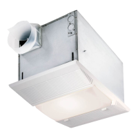
MODEL 665RP
Page 3
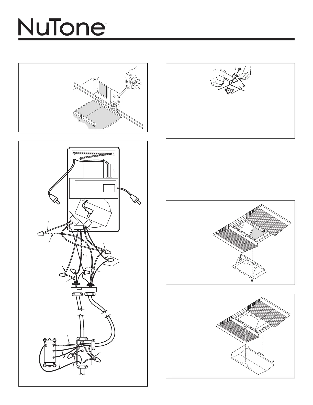
RED
BLACK
120 VAC LINE IN
HEAT
VENT
LIGHT
3 GROUND
WIRES
RED
3 GROUND WIRES
A
B
C
B
C
LIGHT
VENT
HEAT
RED
3 WHITE WIRES
BLACK
BLUE
2 WHITE
WIRES
BLACK
3 WHITE WIRES
A
4. Use a at-bladed
screwdriver
to remove the
proper electrical
knockouts.
5. Connect
electrical
wiring as
shown.
6. Replace the fan assembly removed in Step 4, under “PRE-
PARE THE UNIT” on Page 2. Plug fan assembly into recep-
tacle (C) on the the side of the wiring cover. Direct wires
away from blower inlets.
7. Replace the heater assembly removed in Steps 2, 3, under
“PREPARE THE UNIT” on Page 2. Plug heater assembly
into receptacle (A). Direct wires away from blower inlets.
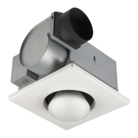
If the switch has not been wired properly and wires need to
be moved:
1. Each wire opening has a release slot.
2. Push a small nail or screwdriver into release slot while
gently removing wire.
3. DO NOT pull any wire out of the switch without using
the release slot. The switch may be damaged.
WIRE OPENING
RELEASE SLOT
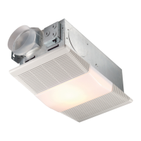
8. Install grille and
light reector.
Plug light into
receptacle (B).
Tighten acorn
nut securely.
Be careful not
to overtighten
nut and deform
reector.
Install a 100
Watt (maximum)
light bulb.
9. Install light
lens. Gently
squeeze tabs
on lens and
insert them
into the slots
in the grille.
 Loading...