Do you have a question about the nvent SPECTRACOOL N280446G050 and is the answer not in the manual?
Describes the operating sequence for heating and cooling modes.
Details on how standard and optional components function within the unit.
Explanation of the standard thermostat operation and setpoints.
Information on the optional remote access control feature.
Details on the optional head pressure control for condenser fans.
Function of the optional 10V transformer for thermal display.
Use of the optional 24V transformer and relay for remote door switch.
Schematic diagram for a generic 115V 1-phase unit.
Schematic diagram for a generic 230V 1-phase unit.
Schematic diagram for a generic 460V 1-phase unit.
Wire diagram for a generic 115V 1-phase unit.
Wire diagram for a generic 230V 1-phase unit.
Wire diagram for a generic 460V 1-phase unit.
Dimensional drawing for units equipped with thermostats.
General introduction to the digital thermostat controller and its capabilities.
Instructions on powering up and initial operation of the controller.
Explanation of the various icons and indicators on the controller display.
Description of the controller keypad symbols, colors, and functions.
Explanation of the main display fields and their meanings.
Details on the status icons displayed on the controller screen.
Guide to viewing and modifying controller settings and parameters.
Details on adjustable heat and cool setpoints and differentials.
Configuration of high/low temperature and door open alarm parameters.
How to view active alarms on the controller display.
Steps to access and review past alarm events stored in the history folder.
Procedure to clear or reset the stored alarm history.
Guide to restoring all control parameters to their original factory settings.
How inlet and outlet temperature data is displayed on the controller.
Explanation of the built-in delay before the compressor can restart.
Information on the normally open dry contact alarm output.
How to connect a dry contact switch for the door open alarm input.
How to physically and logically connect multiple units in PS mode.
Step-by-step guide to configure the controller for Primary-Secondary mode.
Steps to configure controllers for Lead/Lag mode for both units.
Details on establishing communication via USB connection.
Details on establishing communication via Ethernet connection.
Information on downloading software and configuration files.
Guide to using the PC interface tool for unit management.
Detailed steps for establishing and using USB communication mode.
How to view controller data using the A/C unit interface.
Steps to modify temperature settings on the controller via the software.
How to view and modify Ethernet card information and settings.
Detailed steps for establishing and using Ethernet communication mode.
How to manage and monitor multiple units on the network.
Accessing alarm logs using specific support protocols and files.
Schematic diagram for a 115V 1-phase unit with remote access control.
Schematic diagram for a 230V 1-phase unit with remote access control.
Schematic diagram for a 460V 1-phase unit with remote access control.
Wire diagram for a 115V 1-phase unit with remote access control.
Wire diagram for a 230V 1-phase unit with remote access control.
Wire diagram for a 460V 1-phase unit with remote access control.
Dimensional drawing for units equipped with remote access control.
Information on the compressor's maintenance requirements (none).
Details on the inlet air filter, its function, and maintenance.
Step-by-step instructions for filter removal, cleaning, and installation.
Maintenance information for condenser and evaporator fan motors.
Information and procedures related to refrigerant loss and recharging.
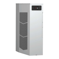
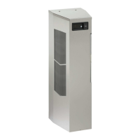
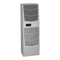
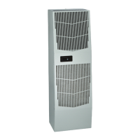
Detailed measurements of the unit's dimensions.
Cooling performance data, including capacity and temperature limits.
Heating capacity information.
Electrical ratings, voltage, and current draw information.
Functional performance data related to airflow and temperature differentials.
A list of replaceable components and their part numbers.
Pressure data for the 50Hz version of the N280416GXXX model.
Pressure data for the 60Hz version of the N280416GXXX model.
Pressure data for the 50Hz version of the N280426GXXX model.
Pressure data for the 60Hz version of the N280426GXXX model.
Pressure data for the 60Hz version of the N280446GXXX model.
Step-by-step troubleshooting checklist for thermostat-controlled units.
Common symptoms and their potential causes for thermostat-controlled units.
Step-by-step troubleshooting checklist for remote access control units.
Common symptoms and their potential causes for remote access control units.
| Cooling Capacity | 2000 BTU/hr |
|---|---|
| Voltage | 115 VAC |
| Power Supply | 1-phase, 60Hz |
| Enclosure Type | NEMA 12 |
| Operating Temperature | 68 to 131 °F (20 to 55 °C) |