MPC5746R Hardware Design Guide, Rev. 1
Example Communication Peripheral connections
NXP Semiconductors48
NOTE
The metal shell of the socket should be connected through a ferrite bead to
the chassis ground.
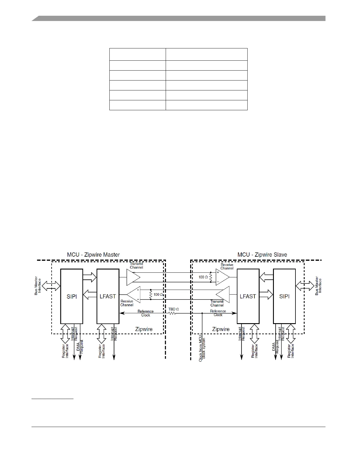
10.4 Zipwire interface
The Zipwire interface is intended to be used to communicate between two nodes implemented on a single
board. The interface uses a “low speed” reference clock that is shared between the two nodes. A
single-ended 10 to 26
1
MHz reference clock is used to generate the Zipwire high speed operation of
approximately 320 MHz. A termination resistor is required at the receiving end of the clock for best
performance of the interface. The value of the resistor depends on the board layout and impedance.
The data signals use a low voltage differential signaling (LVDS) that is internally terminated on the MCU.
The following diagram shows the connection between two devices.
Figure 32. Typical Zipwire hardware interface
The Zipwire interface is a high-speed interface, therefore care should be taken in laying out the signals on
a printed circuit board. The following guidelines are suggested.
5 CAN_SHEILD (optional)
6GND
7CAN_H
8N/C
9 CAN_V+ (optional)
1. 20 MHz is the most commonly used frequency, 10 MHz can also be used. 26 MHz is not recommended.
Table 26. DB-9 Signal Mapping
Pin Number Signal Name

 Loading...


