EVB features
S32R274/372 EVB User Guide, Rev. 0, 08/2018
4 NXP Semiconductors
• Single 12 V external power supply input with four on-board regulators providing all of the
necessary EVB and MCU voltages; Power supplied to the EVB via a 2.1 mm barrel style power
jack or a 2-way level connector; 12 V operation allows in-car use if desired
• Master power switch and regulator status LEDs
• Two 240-way high-density daughter card expansion connectors allowing connection of the MCU
daughter card or a custom board for additional application specific circuitry
• All MCU signals readily accessible at a port-ordered group of 0.1” pitch headers
• RS232/SCI physical interface and standard DB9 female connector
• FlexRAY interface
• LINFlexD interface
• Two CAN interfaces, one configurable to be connected to one out of two CAN modules, and
one connected to a dedicated third CAN module
• Ethernet interface
• Variable resistor, driving between 5 V and ground
• Four user switches and four user LEDs, freely connectable
• Liberal scattering of GND test points (surface mount loops) placed throughout the EVB
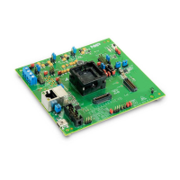
The daughter cards provide the following features:
• MCU (soldered or through a socket)
• Flexible MCU clocking options allow provision of an external clock via SMA connector or 40
MHz EVB clock oscillator circuit. Solder pads on the daughter card allow selection between
these external clocks. SMA connectors (including differential clock input) on CLKIN signal for
easy access.
• User reset switch with reset status LED
• Standard 14-pin JTAG debug connector and 34-pin Nexus Aurora connector
• 10-pin Serial Interprocessor Interface (SIPI) connector
• Gb Ethernet Physical interface IC, with RJ45 connector
• MIPI-CSI2 connector intended for use with Eagle MR3003 RADAR front end EVK (Evaluation
Kit)
• Liberal scattering of ground and test points (surface mount loops) placed throughout the EVB
NOTE
To alleviate confusion between jumpers and headers, all EVB jumpers are
implemented as 2 mm pitch whereas headers are 0.1 inch (2.54 mm). This
prevents inadvertently fitting a jumper to a header.
CAUTION
Before the EVB is used or power is applied, please fully read the
following sections on how to correctly configure the board. Failure to
correctly configure the board may cause irreparable component, MCU or
EVB damage.
 Loading...