3
Operating Instructions and Parts Manual 24616, 24933, 24935, 24939, 24960
3/19
2019 OEMTOOLS
™
29" PORTABLE
TEAR DOWN TRAY
SPECIFIC SAFETY INSTRUCTIONS
AND WARNINGS
WARNING: Thoroughly read and understand the
provided product manual before attempting to use this
product.
WARNING: DO NOT stand on this product. You may
fall, which could lead to personal injury.
WARNING: DO NOT alter this product in any way. Any
added material or components may imbalance the tray,
which could lead to property damage and personal injury.
WARNING: Be mindful of sharp edges/welds while
assembling and operating this Tear Down Tray. Always
wear safety gloves and appropriate safety equipment
while working with tools and equipment.
WARNING: DO NOT exceed weight capacity (see
product specifications). This could lead to product failure
and personal injury.
WARNING: Keep this tray on a level surface. Failure
to do so could cause the tray to tip, and lead to property
damage and personal injury.
ASSEMBLY INSTRUCTIONS
1. Remove all contents from the box and reference the
parts list to ensure that all parts are present.
2. Fasten (2) Casters (I) to each Base Strut (G & F).
Ensure that the square reinforcement on each Caster (I)
is
fully inserted into each square slot on the Base Struts
(G & F).
3. Align the base plate of the Lower Support Column
(J) to the holes on the Base Strut (F). Fasten securely
using the M8 x 16 Hex Bolt (L).
4. Slide the Extended Base Strut (G) into the Lower
Support Column (J). Fasten together with the M8 x 16
Hex Bolts (L).
5. Lay the Top Tray (A) upside down, onto a clean
protected surface. Attach the mounting bracket of the
Upper Support Column (D) to the bottom of the Tray (A)
using the M8 x 16 Hex Bolts (L).
6. Slide the completed Upper Assembly (Step 5) into the
top of the Lower Support Column (J), and secure at the
desired height using the Height Adjustment T-Bolt (E).
SUGGESTED TOOLS FOR ASSEMBLY
1. Metric Socket Set and Ratchet
2. Combination Wrench Set
3. Adjustable Wrench
STORAGE
1. Lower the tray to the lowest height setting for storage.
2. Always store this product on a clean, level surface.
DO NOT store near flammable materials.
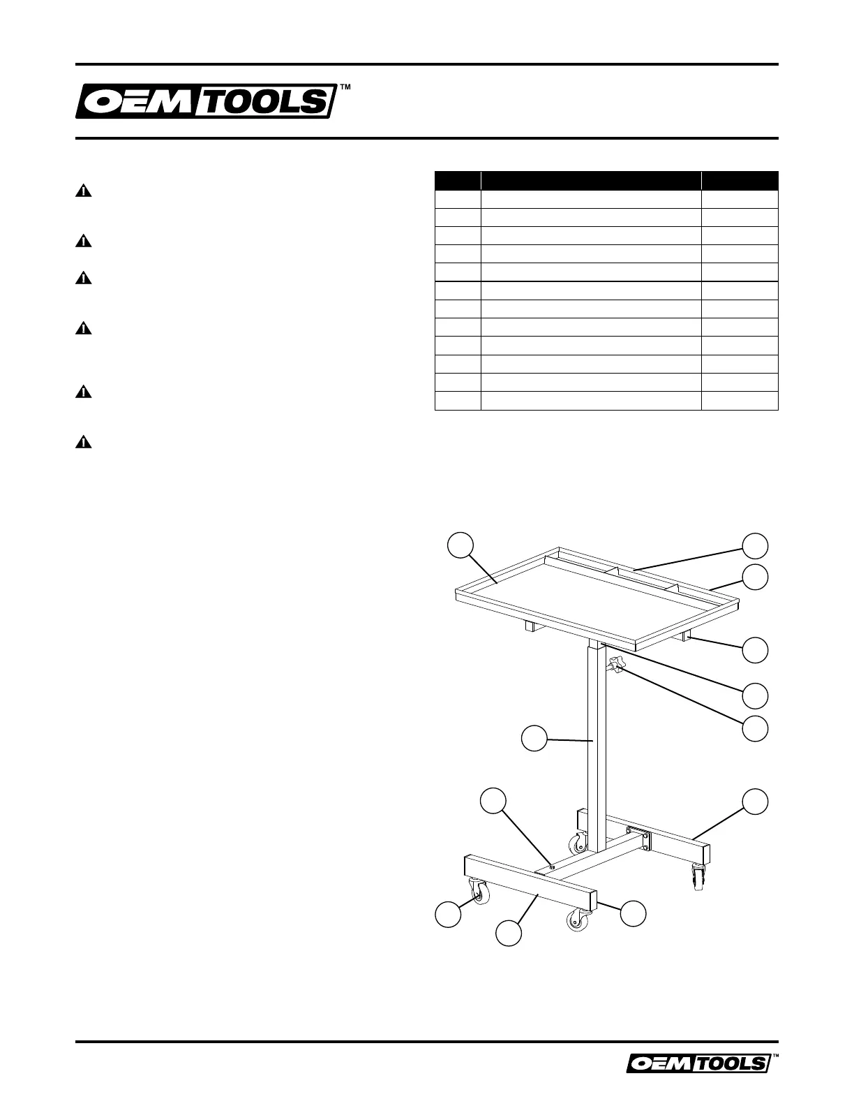
Figure Description Qty.
A
Tray 1
B Protective Rubber Bumper 1
C Small Plastic Insert 4
D Upper Support Column 1
E Height Adjustment T-Bolt 1
F Base Strut 1
H Large Plastic Insert 4
G Extended Base Strut 1
I 2" Caster 4
J Lower Support Column 1
K EVA Mats 4
L M8 x 16 Hex Bolt 9
PARTS LIST
PRODUCT LAYOUT
A
B
C
D
E
F
L
H
J
G
I
K
 Loading...