EasyManua.ls Logo

OHTAKE FM-36 Series User Manual

OHTAKE FM-36 Series
28 pages
To Next Page IconTo Next Page
Page #1 background imageLoading...
Page #1 background image
UIHE
SRI Type
www.ohtake-root.co.jp HP
www.ohtake-root.co.jp
ATTENTION : www.ohtake-root.co.jp is the only web site associated with our company.
We do not have any branches in China.
Operation manual (Maintenance)
自動ネジ供給機
FM-36
Series
Automatic Screw Feeder
FM1MA01M a
Read these instructions for the proper use of this machine.
After having read these instructions, keep them in a convenient
place so you or the operator can refer to them whenever necessary.
02M
Question and Answer IconNeed help?

Do you have a question about the OHTAKE FM-36 Series and is the answer not in the manual?

OHTAKE FM-36 Series Specifications

General IconGeneral
BrandOHTAKE
ModelFM-36 Series
CategoryTools
LanguageEnglish

Summary

Screw Stock Limit and Caution

Screw Stock Limit Diagram

Diagram illustrating the correct and incorrect screw levels in the feeder chamber.

Initial Setup and Precautions

Accessories Checklist

Lists the accessories supplied with the machine for user verification.

Installation Safety

Ensures the machine is installed on a level, stable surface to prevent accidents.

Operational Safety Guidelines

Advises against operating in hazardous environments and disconnecting power when unused.

Operating Precautions and Handling

AC Adapter and Earth Wire Usage

Instructions for using the AC adapter and attaching the earth wire correctly.

Rail Maintenance and Screw Handling

Guidance on rail care and precautions for handling compatible screws.

Foreign Object and Malfunction Warnings

Warnings against inserting foreign objects and procedures for handling operational abnormalities.

Component and Unit Identification

Component Identification

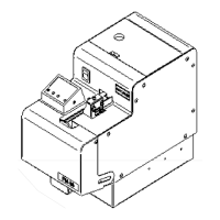
Diagram and labels identifying the various parts of the automatic screw feeder.

Unit Type Identification

Guide to identifying the unit type based on screw size and component labels.

Unit Configuration and Adjustments

Screw Compatibility and Adjustments

Details screw compatibility and necessary adjustments for different screw types.

Machine Preparation and Screw Supply

Screw Supply and Overload Protection

Guidance on screw loading, stock limits, and the machine's overload protection circuit.

Overload Protection and Optional Features

Overload Protection Circuit Actuation

Explains how the overload protection circuit functions and how to reset it.

Optional Screw Supply System

Mentions an optional system for automatic screw supply.

Unloading Screws Procedure

Unloading Screws Procedure

Step-by-step instructions for unloading a metered count of screws from the machine.

LCD Panel Indicators and Settings

LCD Panel Indicators Explained

Describes the functions of the preset count, total count, and LED indicators on the LCD panel.

LCD Panel Settings Adjustment

LCD Panel Settings Adjustment

Instructions for clearing the total count and adjusting preset counts and sound volume.

Component Adjustment Procedures

Brush Check and Adjustment

Procedure for checking and adjusting the brush for proper screw handling.

Passage Plate Check and Adjustment

Guidance on adjusting the passage plate for optimal screw passage.

Holding Plate and Timer Adjustments

Holding Plate Adjustment Procedures

Details vertical and horizontal adjustments for the holding plate to prevent screw issues.

Timer Adjustment for Screw Transfer Speed

Timer Adjustment for Screw Transfer Speed

Explains how to adjust the timer for optimal screw transfer speed based on screw type.

External Output and Maintenance Overview

External Output Signal Line Functionality

Describes the external output signal line for synchronized external device control.

Rail Maintenance and Part Replacement

Rail Groove Cleaning and Adjustment

Instructions for cleaning the rail groove and adjusting rail/escaper disc positions.

Component Replacement Procedures

Replacing the Brush Assembly

Step-by-step guide for replacing the brush assembly for optimal performance.

Replacing the Passage Plate

Procedure for replacing passage plates when using different screw diameters.

Escaper and Rail Assembly Replacement

Replacing the Escaper Unit

Instructions for removing and replacing the Escaper Unit.

Replacing the Rail Assembly

Guide to removing and reassembling the rail assembly, including positional adjustments.

Troubleshooting: Machine Start Issues

Troubleshooting: Machine Not Starting

Diagnoses common causes and solutions when the machine fails to start.

Troubleshooting: Screws Not Flowing (Part 1)

Addresses issues with screws not flowing due to brush, shank, or rail problems.

Troubleshooting: Screw Flow Issues (Part 2)

Troubleshooting: Screws Not Flowing (Part 2)

Further troubleshooting for screws stuck in the rail or unusual postures.

Troubleshooting: Screw Posture and Transfer

Troubleshooting: Screws Fallen or Stuck

Solutions for screws falling into the rail groove or not transferring smoothly.

Troubleshooting: Unusual Screw Posture

Fixes for screws easily passing the window in an unusual posture or due to bin supply.

Troubleshooting: Unloading and Halting Issues

Troubleshooting: Unloading and Halting Issues

Solutions for screws not unloading and abrupt machine halts.

Troubleshooting: Scooping and Noise Issues

Troubleshooting: Scooping and Noise Issues

Addresses issues with scooping stopping and increased machine noise.

Technical Specifications and Screw Reference

Machine Specifications Overview

Provides input/output, dimensions, weight, screw capacity, and accessories.

Applicable Screw Reference Table

Table detailing screw dimensions and compatible screw head shapes.

Replacement Parts Identification

Replacement Parts Identification

Identifies key replacement parts like rail assembly, escaper unit, and passage plate.

Warranty Information

Product Warranty Terms

Outlines the warranty period, applicability, and conditions for users within Japan.

Machine Dimensions

Machine External Dimensions

Provides detailed measurements and diagrams of the machine's external dimensions.