20
CASY TT Operator‘s Guide
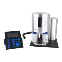
. Pressure System and Power Supply
The pressure system is accommodated in its own cylinder situated behind the measuring unit (not
visible in Figure 5). A no-maintenance vacuum pump, combined with the latest pressure sensors,
guarantees that the vacuum required to aspirate the sample remains constant, irrespective of exter-
nal pressure. The pressure system also interacts with the valves on the measuring unit to control all
uid movements required to empty the vertical tube, replenish the uid system and counter-ush
the measuring capillary.
The power supply for the measuring electronics of the CASY System is housed in the cylinder
arranged outside to the right (see Figure 5). Special lters ensure that the mains power supply is
aorded maximum interference protection.
. Control Panel
The control panel (see Figure 6) consists of a graphic display and a membrane keyboard exhibiting
13 keys. In measuring mode, the graphic display shows the size distribution and indicates the mea-
suring results. All measuring and output parameters can be displayed and adjusted through the
menu control.
The keyboard is divided into three functional areas. The top right-hand area accommodates the keys
used to enter the measuring and output parameters. The bottom right-hand area accommodates
the keys used to control the measuring unit and output the results to the printer. On the left are the
keys used to position the evaluation and the normalization cursors. All keys have a clearly dened
pressure point.
Pressure System and Power Supply
 Loading...