IMPACT ECHO (IE)
www.olsoninstruments.com www.olsonengineering.com
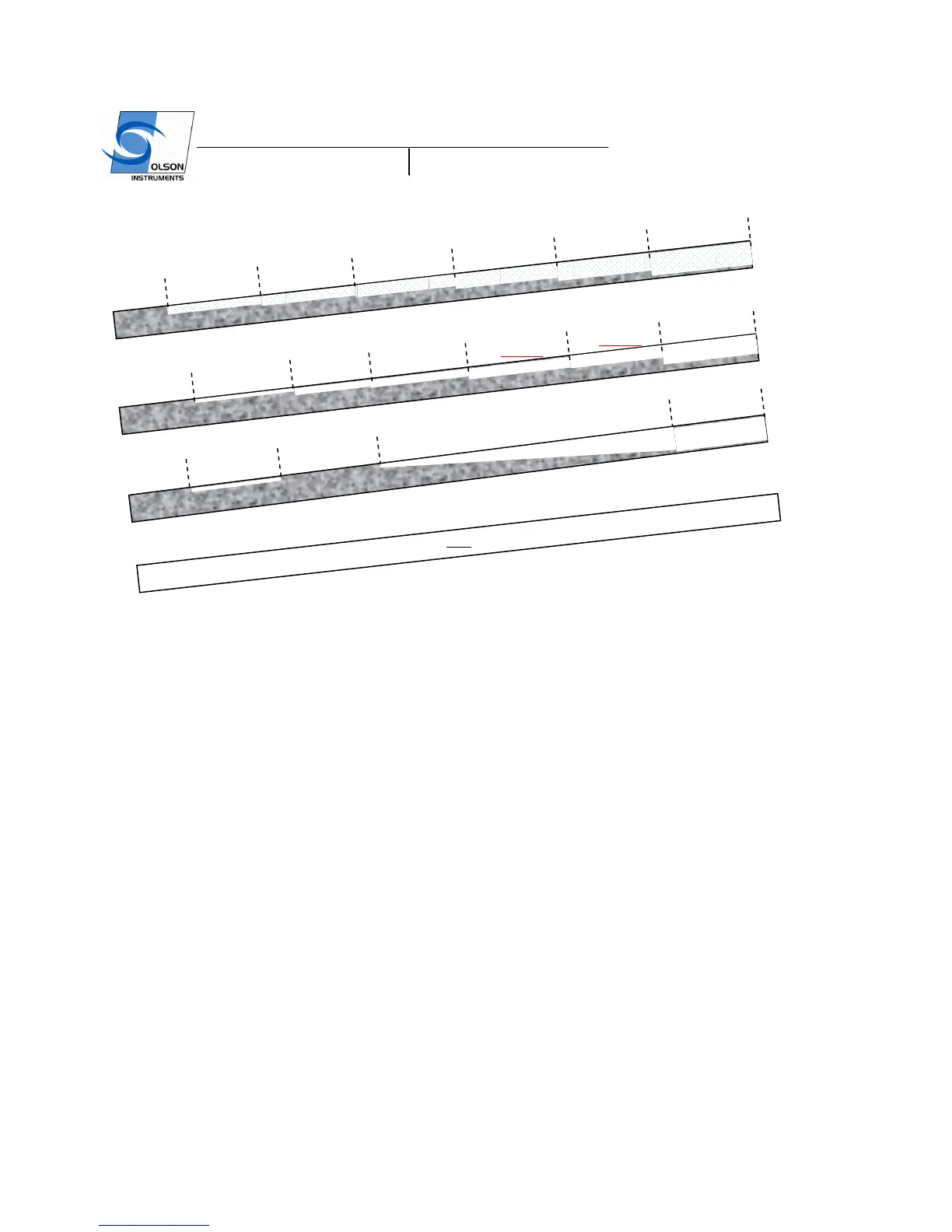
Figure 4b – Design Grout Defects (Styrofoam Voids) in the North Wall in 101.6 mm (4 inch) Metal Ducts
from top down.
Figure 4 – Design Grout Defects
Description of the Mockup Slab and Grout Defects
A mockup concrete slab was designed and constructed at the BAM main campus in Berlin, Germany in
2002 (8). The concrete slab covers an area of 32.8 x 13.1 ft
2
(10 x 4 m²) with a nominal thickness of 11.8
inches (300 mm). The large dimensions of the specimen are necessary to minimize boundary effects on
the measured signals and to establish well-defined defects without interference between them.
The concrete slab contains tendon ducts with varying diameters and grouting defects and different amounts
of post-tension wire strand cables. The slab contains eleven tendon ducts with well defined grouting defects.
The metal ducts were chosen and positioned to represent typical testing situations as they are encountered
in structures. Because of the difficult testing problem, test situations were created without introducing
crossing ducts.
Tendons with the following properties were built in:
- Diameter: 40, 80, 100, and 120 mm (1.57, 3.15, 3.94, and 4.72 inches)
- Concrete Cover: 70, 80, 100, 110, 115, 140, 170, 190 mm (2.75, 3.15, 3.94, 4.33, 4.52, 5.5, 6.7,
7.5 inches) and one sloped duct 50 – 160 mm (1.96 – 6.3 inches) deep
-
Size and location of grouting defects: the size of each of the grouting defects is at least 200 mm
(7.9 inches) in length and represents either a fully ungrouted section (void) or a half-filled duct.
24”
60”
96”
132”
168”
204”
240”
27.375”
63.375”
96”
132”
168”
204”
240”
22”
58”
96”
204”
240”
Void
 Loading...