DMTA-10026-01EN, Rev. D, January 2015
List of Figures
165
List of Figures
Figure i-1 Labels attached to the instrument ..................................................................... 1
Figure i-2 The location of the warning symbol on the top of the instrument ............... 4
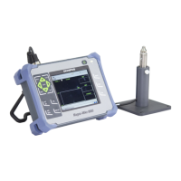
Figure i-3 The Magna-Mike 8600 thickness gage ............................................................ 17
Figure 1-1 Transport case contents ..................................................................................... 21
Figure 1-2 The standard or extended range calibration kit ............................................ 21
Figure 1-3 The Magna-Mike 8600 connections ................................................................. 22
Figure 1-4 The top end connectors ..................................................................................... 23
Figure 1-5 The connectors behind the I/O door ............................................................... 23
Figure 1-6 The RS-232 and VGA Out connectors ............................................................. 24
Figure 1-7 Location of the Magna-Mike 8600 power key and indicator light ............. 25
Figure 1-8 Connecting the charger/adaptor ...................................................................... 26
Figure 1-9 Connecting the DC power plug ....................................................................... 26
Figure 1-10 Removing the lithium-ion battery ................................................................... 28
Figure 1-11 Removing the battery compartment cover and the lithium-ion battery ... 29
Figure 1-12 The alkaline battery holder .............................................................................. 29
Figure 1-13 Installing the microSD card .............................................................................. 30
Figure 1-14 Overview of the Magna-Mike 8600 hardware — Front view ..................... 32
Figure 1-15 Overview of the Magna-Mike 8600 hardware — Back view ....................... 32
Figure 1-16 The charger/adaptor indicator light on the front panel ............................... 33
Figure 1-17 The English, international, Chinese, and Japanese keypads ....................... 34
Figure 1-18 Location of the PROBE and FOOT SWITCH connectors ............................. 38
Figure 1-19 The RS-232 and VGA Out connectors ............................................................. 39
Figure 1-20 The microSD slot and USB port ....................................................................... 40
Figure 1-21 The battery compartment ................................................................................. 42
Figure 1-22 Instrument stand ................................................................................................ 43
Figure 2-1 The main elements of the measurement screen ............................................ 45
Figure 2-2 Example of other elements appearing on the measurement screen ........... 46
Figure 2-3 Menu and submenu example .......................................................................... 47
Figure 2-4 The MEASUREMENT SETUP screen ............................................................. 48
Figure 2-5 The virtual keyboard ......................................................................................... 49
 Loading...
