EasyManua.ls Logo

Olympus U-TV1XC - User Manual

Olympus U-TV1XC
2 pages
Print Icon
To Next Page IconTo Next Page
Loading...
A X 7 9 0 1 U-TV1XC
C-MOUNT CAMERA ADAPTER
U-TV1XC INSTRUCTIONS
This instruction manual is for the Olympus C-Mount Camera Adapter model U-TV1XC, which allows a digital camera
or TV camera to record microscopic images (1X) directly from a microscope.
Before disposing of this product, be sure to follow the regulations and rules of your local government.
2 Assembly
3 Operation
1 System Chart
Fig. 1
Attaching on a UIS Trinocular Tube (Fig. 1)
1. Screw the camera adapter @ securely into the C-mount camera 2.
2. Using the Allen screwdriver provided with the microscope, loosen the
clamping screw 3 on the UIS2 (UIS) trinocular tube and insert the mount
dovetail | of the camera adapter into the camera adapter mount 5 of
the trinocular tube.
3. Tighten the clamping screw 3 firmly.
Adjusting the Microscope
1. Ignite the microscope light source and adjust the microscope modules
to make the microscope ready for observation.
2. Select the camera light path of the trinocular tube.
Adjusting the Camera and Monitor
Perform adjustments such as the color adjustments by referring to the
instruction manuals for the camera and monitor.
} The center of the eyepiece image may not come on the center of
the monitor screen. This phenomenon is due to the mechanism for
adjustment of the camera’s image sensor and not malfunction.
C-Mount Camera Adapter
U-TV1XC
· UIS2 (UIS)
trinocular tube*
· SZX2
· U-TRU
· U-TRUS
· C-mount microscopic digital camera**
· C-mount TV camera**
(With 1-inch or smaller image sensor)
* A UIS2 (UIS) trinocular observation tube (U-TTR-2, U-TR30-2, U-TR30NIR, U-SWTR-3, etc.) can be used. The MVX10
cannot be combined with this product.
** Camera restrictions
· A camera may be unusable if its C-mount plane is lower than the camera body surface.
· If the camera uses an image sensor larger than specified, the image periphery may become dark or obscured.
1
2
5
4
3
Question and Answer IconNeed help?

Do you have a question about the Olympus U-TV1XC and is the answer not in the manual?

Overview

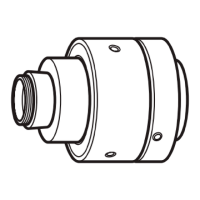
The Olympus U-TV1XC C-Mount Camera Adapter is a specialized accessory designed to facilitate the recording of microscopic images using a digital or TV camera. This adapter enables direct connection of a C-mount camera to a microscope, providing a 1X magnification for image capture.

Function Description:

The primary function of the U-TV1XC is to bridge the gap between a microscope's optical system and a C-mount camera. It allows users to view and record microscopic images on a monitor, making it suitable for documentation, analysis, and presentation purposes. The adapter is designed for use with Olympus UIS2 (UIS) trinocular observation tubes, which include models like U-TTR-2, U-TR30-2, U-TR30NIR, and U-SWTR-3. It's important to note that the MVX10 cannot be combined with this product.

Important Technical Specifications:

  • Magnification: The adapter provides a 1X magnification, meaning the image projected onto the camera sensor is at the same scale as the intermediate image within the microscope's optical path.
  • Camera Compatibility: It is compatible with C-mount microscopic digital cameras and C-mount TV cameras that utilize a 1-inch or smaller image sensor.
  • Trinocular Tube Compatibility: Designed for use with Olympus UIS2 (UIS) trinocular tubes, including specific models such as U-TTR-2, U-TR30-2, U-TR30NIR, and U-SWTR-3. It also supports SZX2, U-TRU, and U-TRUS systems.
  • Parfocality Adjustment Range: The parfocality adjustment, which ensures that the image remains in focus when switching between eyepiece observation and monitor viewing, has a range of ±1.5 mm. If this adjustment is insufficient, users may need to utilize the camera's built-in focusing function.
  • Image Sensor Size Compatibility: The adapter is optimized for image sensors up to 1-inch in size. Using larger sensors may result in the periphery of the image appearing dark or obscured.
  • Reference Data for Image Sensor Sizes:
    • 1-inch camera: 16.16 mm diagonal
    • 2/3-inch camera: 11 mm diagonal
    • 1/2-inch camera: 8.08 mm diagonal
    • 1/3-inch camera: 6 mm diagonal
    • 1/4-inch camera: 4 mm diagonal
  • Magnification on Monitor Calculation: The magnification observed on the monitor can be calculated using the formula: (Objective power) × (Camera adapter power (1X)) × (Diagonal size of monitor screen / Diagonal size of image sensor). It's important to remember that actual diagonal lengths of monitors and image sensors may vary slightly between manufacturers.

Usage Features:

  • Assembly:
    1. The camera adapter is screwed securely into the C-mount camera.
    2. Using an Allen screwdriver, the clamping screw on the UIS2 (UIS) trinocular tube is loosened.
    3. The mount dovetail of the camera adapter is inserted into the camera adapter mount of the trinocular tube.
    4. The clamping screw is then tightened firmly to secure the adapter in place.
  • Microscope Adjustment:
    1. The microscope's light source should be ignited, and the microscope modules adjusted for observation.
    2. The camera light path of the trinocular tube must be selected.
  • Camera and Monitor Adjustment: Users should perform necessary adjustments, such as color calibration, by referring to the instruction manuals for their specific camera and monitor. It's noted that the center of the eyepiece image may not always align with the center of the monitor screen, which is attributed to the camera's image sensor adjustment mechanism rather than a malfunction.
  • Parfocality Adjustment: This feature eliminates the need to refocus when switching between eyepiece observation and monitor viewing.
    1. Focus on the specimen using a high-power objective through the eyepieces.
    2. Switch to a low-power objective, select the camera light path, and observe the monitor image.
    3. Loosen the clamping screws on both the trinocular tube and the camera adapter. While observing the monitor, hold the top of the camera adapter and turn its bottom to adjust the focus. The fixing screw of the camera adapter may not always be on the front; users should check all sides if it's not immediately visible.
    4. Once the monitor image is in focus, tighten the clamping screws firmly.
  • Centering Adjustment: This adjustment helps reduce image deviation between different objectives.
    1. Loosen the "LOCK" screw on the camera adapter using an Allen screwdriver until it projects 3-4 mm from the surface. Avoid loosening it too much to prevent it from slipping out.
    2. Engage a higher-power objective and position the target region of the specimen at the center of the monitor image.
    3. Engage a lower-power objective and use the two "CENTERING" screws with the Allen screwdriver to bring the target region to the center of the monitor image. Repeat steps 2 and 3 as needed for improved accuracy.
    4. Tighten the "LOCK" screw firmly.
  • Image Pickup Areas: The manual provides an illustration showing the field of view of eyepieces with a Field Number (FN) of 22 and the corresponding image pickup areas for 1-inch, 2/3-inch, and 1/2-inch image sensors, demonstrating how different sensor sizes capture the image.

Maintenance Features:

  • Disposal: Users are instructed to follow local regulations and rules for proper disposal of the product.
  • Camera Restrictions: Users should be aware that a camera might be unusable if its C-mount plane is lower than the camera body surface. Additionally, using an image sensor larger than specified can lead to dark or obscured image peripheries.

The Olympus U-TV1XC C-Mount Camera Adapter is a robust and essential tool for integrating C-mount cameras with Olympus microscopes, designed to provide clear and accurate digital imaging of microscopic specimens.

Olympus U-TV1XC Specifications

General IconGeneral
BrandOlympus
ModelU-TV1XC
CategoryAdapter
LanguageEnglish

Related product manuals