Do you have a question about the OM POWER OM3006 and is the answer not in the manual?
Lists technical specifications like frequency coverage, power output, impedance, and protection circuits.
Details the tetrode GU78b, grounded-cathode circuit, input impedance, and broadband input circuitry.
Identifies key internal components visible from the top, including the tetrode, blower, and circuits.
Explains control and monitoring circuits for safety and malfunction detection.
Guides on connecting coaxial cables for input and output, specifying cable types and connectors.
Identifies rear panel connectors such as mains plugs, fuses, key in/out, and RF output/input.
Details control cable functionality, PTT switching, and transceiver connections.
Explains mains connection, phase requirements, and power delivery capacity.
Emphasizes proper grounding with copper cable for safety and signal integrity.
Describes the operation of centrifugal blowers for amplifier cooling during and after use.
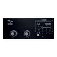
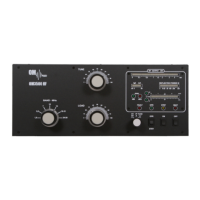
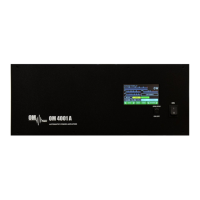
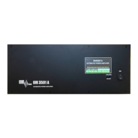
Identifies and describes front panel controls like TUNE, LOAD, ON/OFF, and indicators.
Explains the process of tuning the amplifier for optimal performance and linearity.
Lists the meanings of various flashing LED patterns indicating specific faults.
| Maximum VSWR | 2:1 |
|---|---|
| Input Impedance | 50 Ω |
| Output Impedance | 50 Ω |
| Suppression of Harmonics | -50 dB |
| Power Supply | 220 V AC, 50/60 Hz |
| Cooling | Forced air cooling |
| Operating Modes | SSB, CW, AM, FM |
| Power Output | 3000 W PEP |