4
UTILIZZO USE
16
OMCA S.r.l - Via Curiel, 6 - 42025 - Cavriago (RE) - ITALY
Telefono: +39 0522 943502 / +39 0522 943503 - Website: www.omcasrl.it - E-mail: info@omcasrl.it
4.4
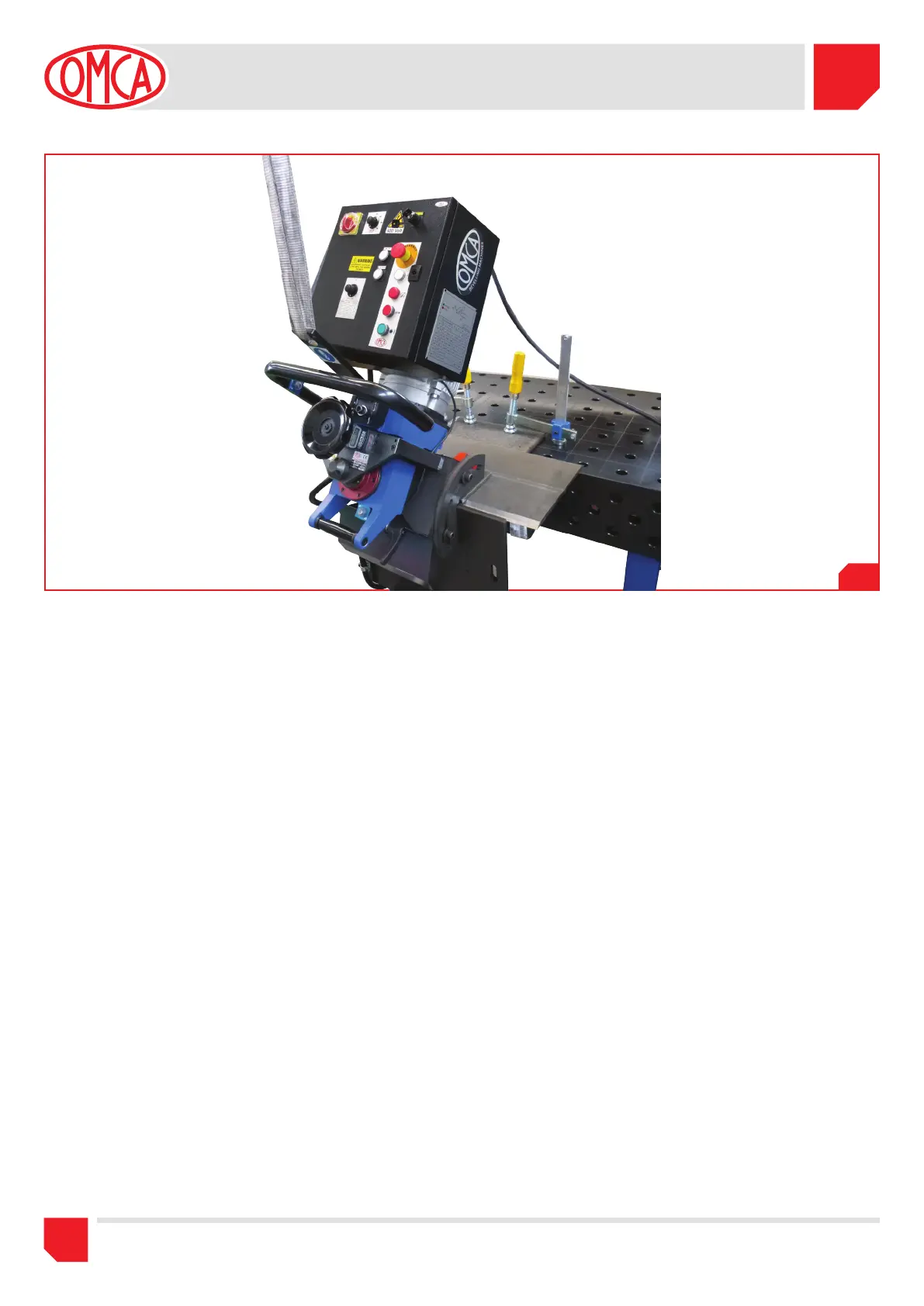
5) Ruotare l’interruttore generale in posizione ON(1)(Fig.4.1 pos.C).
6) Abbassare o alzare le ruote di trascinamento (Fig.2.1 pos.2)
mediante i pulsanti SALITA e DISCESA (Fig.4.1 pos.S e pos.R)
per ottenere lo spazio necessario per l’inserimento della lamiera.
7) Posizionare l’inizio della lamiera in corrispondenza delle prime
ruote trainanti come indicato in (Fig.4.2 pos.B).
IMPORTANTE !! la fresa non deve essere a contatto con la lamiera.
Inoltre fare attenzione che il pezzo sia ben aderente alle squadre
di posizionamento
(Fig.4.2 pos.C)
per una corretta e uniforme
smussatura lungo tutto il bordo.
8) Premere il pulsante SALITA RUOTE (Fig.4.1 pos.S) per stringere
automaticamente le ruote di avanzamento contro la lamiera da
lavorare, l’accensione della spia posto all’interno del pulsante
conferma il completamento dell’operazione
.
9) Regolare la dimensione dello smusso come indicato nel capitolo 4.4.
10) Premere il pulsante di start (Fig.4.1 pos.E), regolare la velocità
della fresa (Fig.4.1 pos.P) e ruotare lentamente il potenziometro
che regola la velocità di avanzamento (Fig.4.1 pos.O) fino alla
posizione di 0.3 (m/min).
Tenendo le mani ben salde sulla maniglia, accompagnare la
macchina durante l’inizio della lavorazione.
11) In base alla dimensione dello smusso e del tipo di materiale è
possibile aumentare la velocità di avanzamento quando tutte le
ruote trainano sulla lamiera.
5) Turn the general switch to the position ON (1)(Pic.4.1 pos.C).
6) Lower or raise the feed wheels (Pic.2.1 pos.2) with the buttons
UP and DOWN (Pic.4.1 pos.S and pos.R) to obtain the necessary
space for the metal sheet enter.
7) Place the beginning of the metal sheet in correspondence of the
first feed wheels as indicated on (Pic.4.2 pos.B).
IMPORTANT !! the cutter must not be in contact with the metal
sheet. Moreover, pay attention that the metal sheet is well fitted
to the positioning plate (Pic.4.2 pos.C) for a correct and uniform
chamfering on the whole edge.
8) Push the button UP WHEELS (Pic.4.1 Pos.S) to automatically
tighten the feeding wheels against the metal sheet; the light inside
the button confirms the completing of the operation.
9) Adjust the chamfer dimension as described in chapter 4.4.
10) Press the start button (Pic.4.1 pos.E), adjust the speed of the
cutter (Pic.4.1 pos.P) and slowly turn the potentiometer to adjust
the feed speed (Pic.4.1 pos.O) to the position of 0.3 (m/min).
Keeping your hands firmly on the handle, drive the machine
during the beginning of job.
11) Based on the chamfer dimension and the type of material, it is
possible to increase the feed speed when all the wheels run on the
metal sheet.
 Loading...