Starter
Motor
Relay
7.5 Amp
Siren
Pin-Switch (+)
Battery
+
Pin-Switch (-)
Pin-Switch (-)
Relay
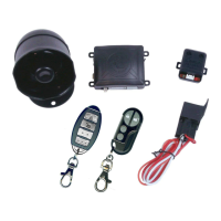
K-9 Mundial
By Omega Research & Development
Orange = Starter Kill -
Grey = Auxiliary Output -
Red/White = Flashing Light Input (+/-)
White = Flashing Light Output
White = Flashing Light Output
Brown = Siren / Horn (+/-)
Violet = Door Input +
Black = Ground
Blue = Trigger Input -
Yellow = Accessory +12V
Green = Door Input -
Red = +12 Volts
Door Lock Port
Sensor
(-) (+)
Horn Siren
Page 25
Valet/Override
Switch
LED Status
Indicator
Page 24
7.5 Amp
15 Amp
Left Parking Lights
Right Parking Lights
Page 26
Orange Wire - (Negative Output For Optional Starter Interrupt): The Orange
wire is for a starter disable socket and relay. The function of this wire is to provide
a 500mA - Ground Output whenever the security system is in an armed state. This
output supplies - Ground to one side of the relay's coil. The other side of the relay
coil will be supplied with +12 Volts from the ignition switch, but only if the ignition
switch is turned to the "start" position. If this occurs, the coil will energize, activating
the relay, which in turn will open the starter circuit. The starter interrupt prevents
the vehicle from starting only if the alarm is armed (including while the alarm is
activated), and will draw current from the vehicle's electrical system only if an
attempt is made to start the vehicle.
CONNECTION: To interrupt the vehicle's starter circuit, the starter wire must be
located and cut. It is recommended that this connection be done as close to the
ignition switch as possible. Use a voltmeter, not a test light, to find the correct wire,
which is the wire from the ignition switch to the starter solenoid.
CAUTION! Avoid
the airbag circuit! Improper use of a test light can cause deployment of the airbag,
which may result in bodily injury! Test lights can also damage on-board computers
and associated sensors.
The starter wire will read +12 Volts only when ignition key is in "start" position
(cranking the engine). Cut this wire at a suitable location. Confirm that this is the
correct wire by turning the ignition switch to the "start" position. The starter should
not engage.
Page 27
Configuring a Starter Disable using the Socket & Relay.
Ignition
Switch
Cutting the vehicle's
Starter wire will leave
two sides- the Ignition
Switch side and the
Starter Solenoid side.
87a
30
87
85
86
C O I L
Starter Disable Socket
White wire to the Starter
Solenoid side of the cut
Starter wire.
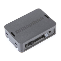
Security
System
Control
Module
Socket
Orange
Wire
Control
Module
Orange wire
Starter
Solenoid
Starter Disable Socket Red wire
to the Ignition Switch side of the
cut Starter wire.
 Loading...