5
This shaft will aligned both base’s discs. Insert
the bolt (part 1 fig.7) and make sure to use the
washers (part 2 and 4 fig 7.) between the bolt
and the disc. On the opposite side insert the
washer and nut. Use the supplied nut wrenches
(top-right fig.7). One should hold the bolt in
place with one wrench (to avoid it from
rotating) and tighten the nut with the other
wrench. Make sure that at the end of this
procedure the discs rotate freely, but no
noticeable wobbling between them exists. Place
the assembled set so that the rubber feet are
now touching the ground. Now it is time to
install the black metal bearing cylinders. These
are used to support the optical tube on top of
the Dobson base. Use the supplied 4 flat head
bolts #7 as shown in fig. 9. Use the supplied
Allen wrench for this matter. Make sure the
bearing cylinders match the correct side panel.
The cylinder-shaped ones should be fitted to
the right panel while the T-shaped (fig. 11)
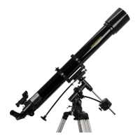
should be fitted to the left panel. Please tighten
all 4 flat-head screws firmly. Place the tube on
the base (fig. 12). The tube should now tilt
freely. 4. What is the Balance Adjustment
System and how to use it? The balancing
system is only required when the optical tube is
out of balance – tilts either to the front or the
back - and additional friction is required. Using
a heavier eyepiece for example may tilt the
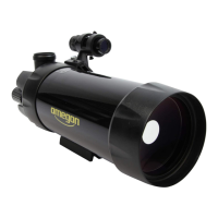
telescope tube to the front. On the surface of
the left panel there is also a black metal disc (#6
–fig.1). The disc is part of the telescope’s
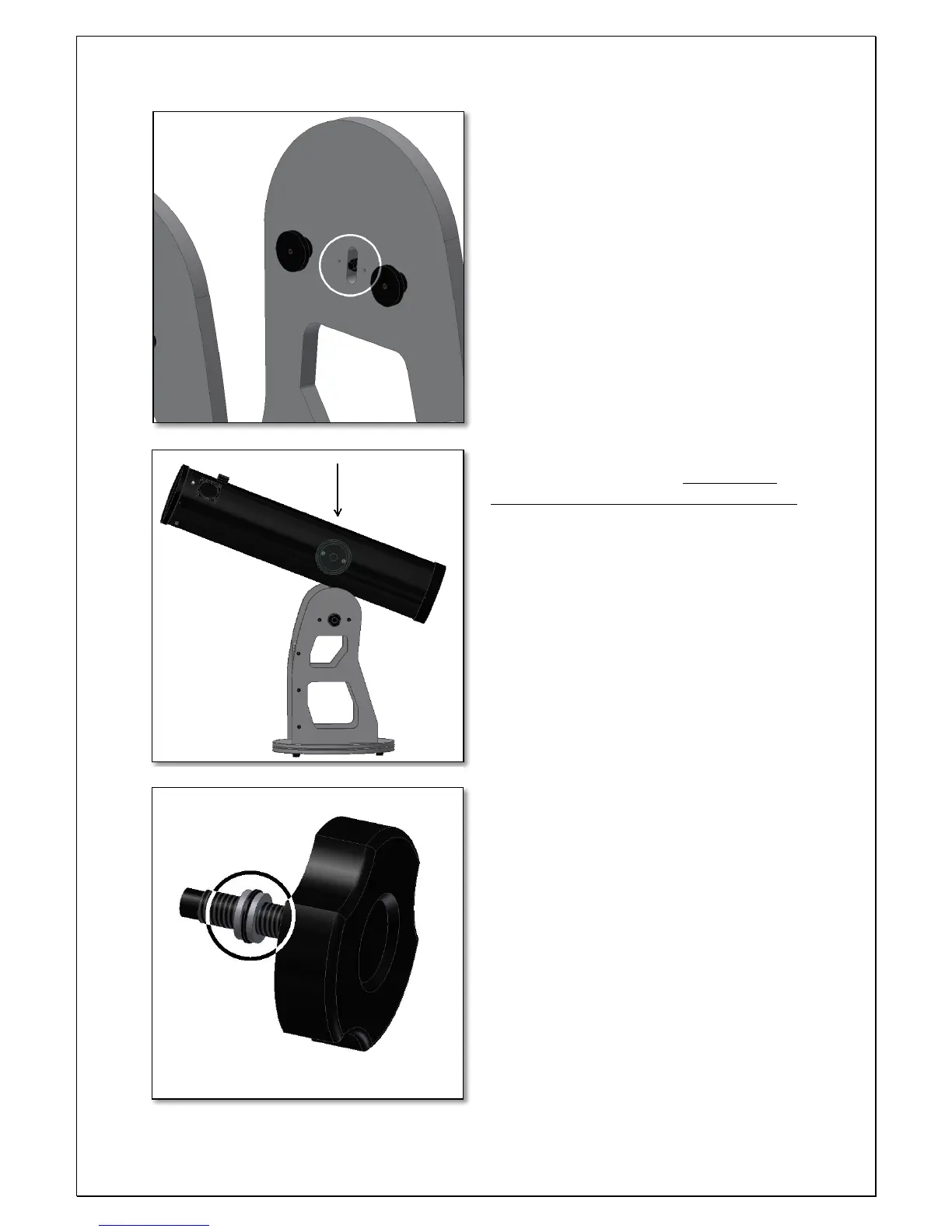
balancing system. The balancing system includes
the metal disc and the supplied hand-knob (fig.
13). Thread the Knob to the disc #1 – fig.10.
Make sure the washer set is included (fig. 13).
Keep on threading until the plastic tip hits the
telescope’s side bearing (fig. 14). Inspect the
plastic tip as shown in figure 14. The knob’s
plastic tip should be hitting the telescope’s
plastic side bearing. We want this plastic tip to
be inside the telescope’s bearing recess as
shown in figure 14 - bottom. The telescope’s left
panel with this disc was previously adjust but
might require further adjustment. 4.1. How to
adjust the friction? Release (without
 Loading...