Rea
t
ese
nstruct
ons care
u
y. No guarantee w
e a
owe
for wrong installation.
INSTALLATION AND USE OF THE ROOFLIGHT
CONTENTS MOUNTING SET
Screw DIN 7981 - 4,2 x 38 ................................................................ 4
Washer DIN 125 - M5......................................................................... 4
Screw DIN 7982 - 4,2 x 38 ................................................................ 4
Mounting clip...................................................................................... 4
Screw DIN 7981 - 3,5 x 32 ................................................................ 2
Operating knob with square shaft 6 x 70 mm................................ 1
Extension tube .................................................................................... 4
INSTALLATION ROOFLIGHT (fig.1)
To install the OMNIVENT a roof thickness of 25 to 60 mm is required. For
the OMNIVENT 12V (with ventilator) a thickness of 27 to 60 mm is
required.
1. Make a 400 x 400 mm hole and clean the surroundings (fig.2).
2. Put an acid free sealing material that sticks to A.B.S. under the edge of
the upperframe (C) (fig. 3).
3. Install the upper part (A+C) with the hinge in the driving direction.
4. Fix the exterior frame to the roof by using a mounting clip in the
middle of each side (see fig. 5). Use screw DIN 7982 - 4,2 mm with
length according to the table. Do not tighten too much, so that no
deformation of the frame can occur.
5. For OMNIVENT 12V, with ventilator: Connect 12V DC to the lead-in wires
of the ventilator as described below.
6. Put the operating knob with the square shaft into the inner frame and
secure it with the O-ring (fig. 9).
Remark: The delivered operating knob with square shaft is suitable for
roofthicknesses from 25 up to 50 mm. For a roofthickness over 50 mm,
use the kit for roof thickness 40-60mm with a square shaft of 90 mm
length.
7. Install the inner frame (E) with the square shaft (D) of the knob in the
hole of the mecanism. For a roofthickness 40mm, put first on the
screw tube in each corner of the exterior frame (C) an extension tube.
This will make the screwing of the interior frame easier (fig. 7).
8. Fix the interior frame to the exterior frame in the corners by using the
screws DIN 7981 - 4,2mm with length according to the table (fig. 6).
9. Clips the flynet (F) inside the frame. (The OMNIVENT 12V with fan has
has an integrated flyscreen).
10. Clips the roller blind (G) on and secure it with 2 screws DIN 7981 3,5 x
32 (fig. 4).
USE ROOFLIGHT
- Close the lid before driving.
- To take away the roller blind, unscrew and take off.
OPTIONS
- 12V fan. Prod.nr. 23 0150 00.
- 12V fan with thermostat. Prod.nr. 23 0151 00.
- Kit for roof thickness 40-60mm. Prod. nr. 23 0200 00.
INSTALLATION AND USE OF THE VENTILATOR
INSTALLATION OF THE VENTILATOR
A ventilator 12V - 20 min_/min (700 cft/min.) can be installed
afterwards to the OMNIVENT rooflight.
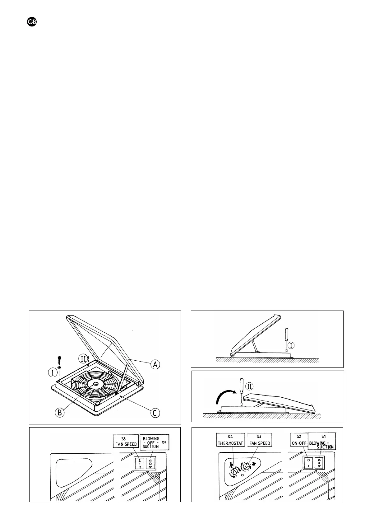
1. Fix the ventilator (B) to the outer frame (C) by screws 4,2 x 25 (fig.
10). To allow to insert the 2 screws at the frontside, open the lid for
about 5 cm, unscrew the hinge profile and slide the lid backwards. See
fig. 12.
2. Connect 12V DC to the lead-in wires of the ventilator via a slow fuse of
10A in the + conduction. The connector can be stored in the chamber
near the operating device (fig. 8). For the fan with continuous speed
regulation: red wire: positive , black wire: negative .
Provided the wiring is done correctly, the installation will meet EMC
standards 89/336/EEC. The fan has approval KBA no. 19303 for
installation on vehicles
USE OF 3 SPEEDS VENTILATOR (fig. 13)
- The ventilator is started by the switch S5 [< 0 >]: or "extract" or "intake"
- The airflow is adjusted by using the switch S6 [2 1 3]:
* position 1 = 7 m3/min. (245 cft/min.) (10 W - 0,8 A)
* position 2 = 12 m3/min. (420 cft/min.) (25 W - 2,2 A)
* position 3 = 20 m3/min. (700 cft/min.) (60 W - 5 A)
Remark :
Do not start immediately at the highest speed level. The fuse could be
blown by the high current peak (15A).
USE OF THE VENTILATOR WITH CONTINUOUS SPEED REGULATION AND
THERMOSTAT (fig. 14)
- The fan is turned on and off by using the switch S2 [0 1].
- The fan is set on ‘extract’ or ‘intake’ by using the switch S1 [< 0 >].
- The speed can be regulated continuously by means of the small S3
button:
* MIN. = 3 m_/min. (100 cft/min) (2,5 W - 0,2 A)
* MAX. = 20 m_/min. (700 cft/min) (60 W - 5 A).
- The switch temperature of the thermostat can be determined by the
small S4 button. It can be set continuously between 15° C (pos. 1) and
65° C (pos. 7). Position 2-3 corresponds to a 25 to 30° C temperature.
When the programmed temperature is reached, the fan automatically
switches on (provided that the switch S2 is in position 1).
- Put the small thermostat button S4 in position 0 to prevent the
operation of the thermostat. In this position the fan can be used in
temperatures below 15° C.
Remark:
In longer absence, programm the fan at reduced speed when using the
thermostat. The risk of an empty battery will be avoided.
MAINTENANCE
The ventilator grid can be taken off for cleaning.
10
11
12
13 14


 To Next Page
 Loading...