Chapter 10
10-61
Appendices
Note 1. The values in parentheses indicate initial values when initialized in 3-wire sequence.
Note 2. Set H5-01 to 0 to disable Inverter responses to RS-422A/485 communications.
Note 3. Values in parentheses are for Asian model Inverters.
Note 4. This parameter is not supported by the Asian model Inverters.
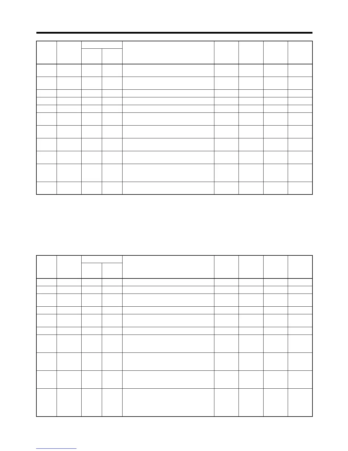
■ Protective Function Parameters
H5-04 0428 04 28 Stopping method after communication
error
0 to 3 1 3 No
H5-05 0429 04 29 Communication error detection selec-
tion
0, 111No
H5-06 042A 04 2A Send wait time 5 to 65 1 ms 5 No
H5-07 042B 04 2B RTS control ON/OFF 0, 1 1 1 No
H6-01 042C 04 2C Pulse train input function selection 0 to 2 1 0 No
H6-02 042D 04 2D Pulse train input scaling 1000 to
32000
1 Hz 1440 Yes
H6-03 042E 04 2E Pulse train input gain 0.0 to
1000.0
0.1% 100.0 Yes
H6-04 042F 04 2F Pulse train input bias −100.0 to
100.0
0.1% 0.0 Yes
H6-05 0430 04 30 Pulse train input filter time 0.00 to
2.00
0.01 s 0.10 Yes
H6-06 0431 04 31 Pulse train monitor selection 1, 2, 5,
20, 24,
36
12Yes
H6-07 0432 04 32 Pulse train monitor scaling 0 to
32000
1 Hz 1440 Yes
Con-
stant
Regis-
ter num-
ber
(hex)
Class 64 (hex) Name Setting
range
Setting
unit
Default
setting
Write
during
opera-
tion
In-
stance
At-
tribute
L1-01 0480 04 80 Motor protection selection 0 to 3 1 1 No
L1-02 0481 04 81 Motor protection time constant 0.1 to 5.0 0.1 min 1.0 No
L1-03 0482 04 82 Alarm operation selection during motor
overheating
0 to 3 1 3 No
L1-04 0483 04 83 Motor overheating operation selection 0 to 2 1 1 No
L1-05 0484 04 84 Motor temperature input filter time con-
stant
0.00 to
10.00
0.01 s 0.20 No
L2-01 0485 04 85 Momentary power loss detection 0 to 2 1 0 No
L2-02 0486 04 86 Momentary power loss ridethru time 0.0 to 2.0 0.1 s Depends
on
capacity.
No
L2-03 0487 04 87 Min. baseblock time 0.1 to 5.0 0.1 s Depends
on
capacity.
No
L2-04 0488 04 88 Voltage recovery time 0.0 to 5.0 0.1 s Depends
on
capacity.
No
L2-05 0489 04 89 Undervoltage detection level 150 to
210 (150
to 420)
(See
note 1.)
1 V 190
(380)
(See
note 1.)
No
Con-
stant
Regis-
ter num-
ber
(hex)
Class 64 (hex) Name Setting
range
Setting
unit
Default
setting
Write
during
opera-
tion
In-
stance
At-
tribute
 Loading...


