Chapter 10
10-67
Appendices
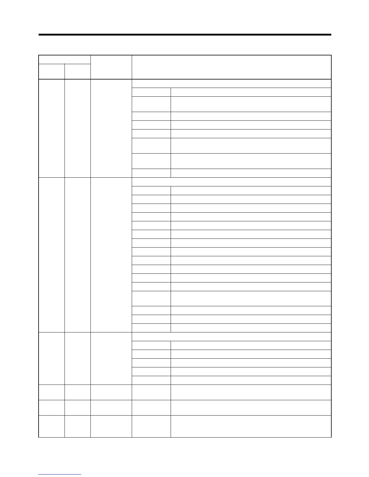
10-6-2 Inverter Monitoring Functions (Read)
Class 64 Register No.
(Hex)
Contents
In-
stance
At-
tribute
00 20 0020 Inverter status
Bit 0 Operation 1: Operating 0: Stopped
Bit 1 Reverse operation 1: Reverse operation 0: Forward opera-
tion or stopped
Bit 2 Inverter startup complete 1: Completed 2: Not completed
Bit 3 Error 1: Error
Bit 4 Data setting error 1: Error
Bit 5 Multi-function contact output (terminal M1-M2) 1: ON 0:
OFF
Bit 6 Multi-function contact output (terminal M3-M4) 1: ON 0:
OFF
Bits 7 to 15 Not used.
00 21 0021 Error details
Bit 0 Overcurrent (OC), ground fault (GF)
Bit 1 Main circuit overvoltage (OV)
Bit 2 Inverter overload (OL2)
Bit 3 Inverter overheat (OH1)
Bit 4 Not used.
Bit 5 Fuse blown (PUF)
Bit 6 PID feedback reference lost (FbL)
Bit 7 External error (EF, EFO)
Bit 8 Hardware error (CPF)
Bit 9 Motor overload (OL1) or overtorque 1 (OL3) detected
Bit 10 Not used.
Bit 11 Main circuit undervoltage (UV) detected
Bit 12 Main circuit undervoltage (UV1), control power supply error
(UV2), inrush prevention circuit error (UV3)
Bit 13 Not used.
Bit 14 RS-422A/485 communications error (CE)
Bit 15 Operator disconnected (OPR)
00 22 0022 Data link status
Bit 0 Writing data
Bits 1 and 2 Not used.
Bit 3 Upper and lower limit errors
Bit 4 Data integrity error
Bits 5 to 15 Not used.
00 23 0023 Frequency
reference
Monitors U1-01 (Unit set with o1-03.)
00 24 0024 Output fre-
quency
Monitors U1-02 (Unit set with o1-03.)
00 25 0025 Output volt-
age refer-
ence
Monitors U1-06 (0.1-V units)
 Loading...


