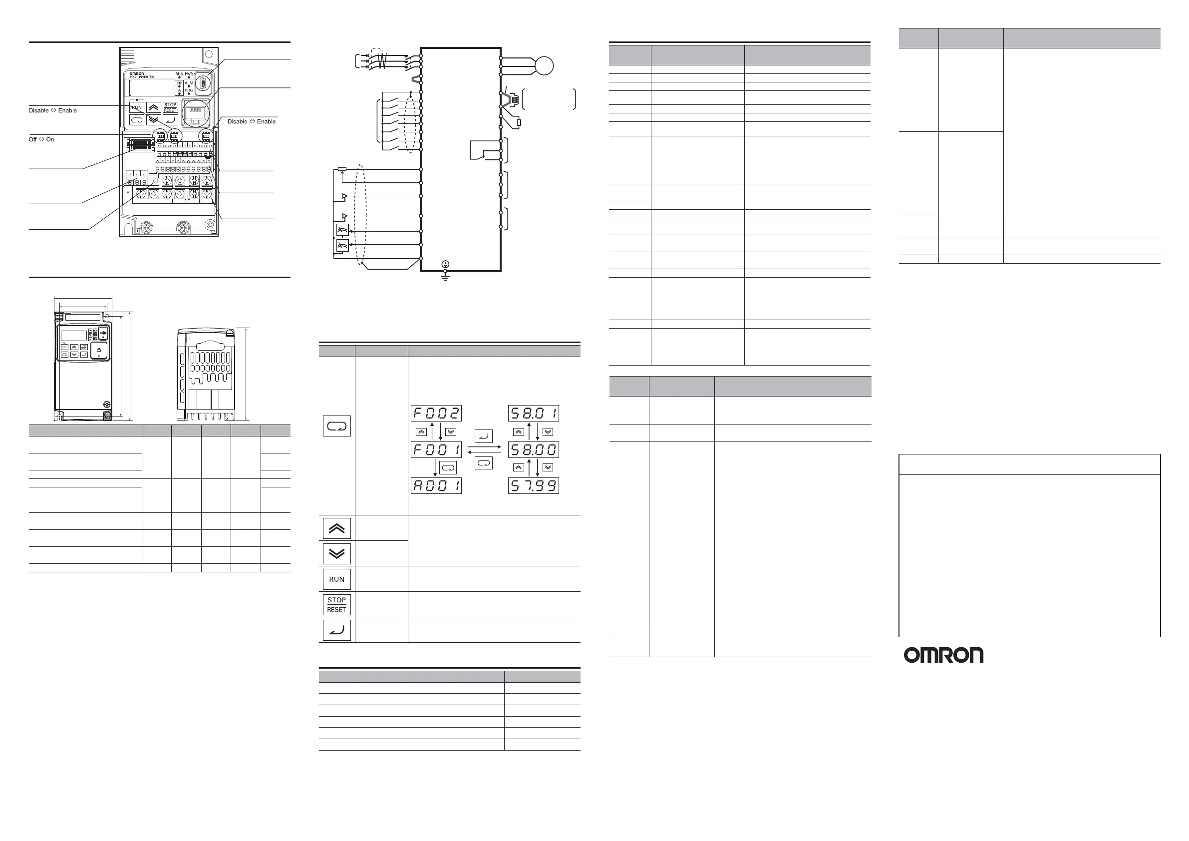
Installation and Wiring
Dimensions
A2150-V1 175336
AB007-V1, AB015-V1, AB022-V1
A2015-V1, A2022-V1, A4007-V1
A4015-V1, A4022-V1, A4030-V1
350192220
[mm]
A2110-V1
A4110-V1, A4150-V1
180 160 296 284 175
A2055-V1, A2075-V1
A4055-V1, A4075-V1
140 122 260 248 155
A2037-V1
A4040-V1
140 128 128 118 170.5
A4004-V1
108 96 128 118
170.5
143.5
A2007-V1
AB004-V1
A2004-V1
AB001-V1, AB002-V1
A2001-V1, A2002-V1
3G3MX2-
WW1H H1 D
68 56 128 118
145.5
122.5
109
W1
W
H1
H
D
Standard Connection Diagram
*1. Connect a single-phase 200V AC input to terminals L1 and N.
*2. Factory default settings for relay output are NC contact for MA and NO
contact for MB.
Single-phase/
3-phase
power supply
Short-circuit bar
Short-circuit bar
Motor
ELB
MC
R/L1(L1) *1
S/L2
T/L3(N) *1
MC
S7/EB
S5/TH
S4/GS2
S3/GS1
S2
S1
FS
FV
FI
RP
AM
MP
RS-
RS+
PC
P1/EDM
P2
MB
MA
N/-
SC
S6
P24
DCL
PSC
SC
Multi-function input
(7 contacts)
Multi-function output
(2 terminals)
Multi-function contact output *2
Braking resistor
WRN
10V DC power supply
(10 mA max.)
Analog voltage input
0 to 10 V (10 bits)
Analog voltage output
0 to 10 V (10 bits)
Class D (200-V class)
Class C (400-V class)
Analog current input
4 to 20 mA (10 bits)
Pulse train input
5 to 24 V DC
(32 kHz max.)
Pulse train output
0 to 10 V (32 kHz max.
)
Serial communications
port
(RS485/Modbus)
RB
P/+2
+1
W/T3
V/T2
U/T1
M
3~
To connect the DC
reactor (DCL), remove
the short-circuit bar.
In case two or more
inverters are connected
to common I/O wiring,
special care to be taken
to avoid closed loop
circuit. Please refer to
user’s manual.
Keys
Name Description
Mode key
Increment
key
Decrement
key
RUN key
STOP/RESET
key
Enter key
x
Moves to the next function mode when the parameter
number is displayed.
x
Cancels the set data in the process of change and
displays the parameter number when the parameter
data is displayed.
Status transition
Changes the set values, parameters and Commands
Starts the operation. Forward / Reverse rotation
depends on the ‘F004’ setting.
Stops the operation. Functions as the Reset key
if an error occurs.
x
Switches the display from the parameter number to
set data.
x
Enters and stores the set data.
* Press and hold the Mode key for 3 seconds or more
to jump to the d 001 data display.
Related Manuals
W453-E1
I580-E1
I563-E1
I574-E1
I582-E1
I581-E1
Name Catalog No.
CX-Drive Operation Manual
DriveProgramming User’s Manual
Regenerative Braking Unit 3G3AX-RBU User’s Manual
EtherCAT Communication Unit User’s Manual
CompoNet Communication Unit User’s Manual
DeviceNet Communication Unit User’s Manual
Parameter
No.
Function name Monitor or data range
d001 Output frequency monitor 0.00 to 400.0 [Hz]
d002 Output current monitor 0.0 to 655.3 [A]
d003 Run direction monitor F: forward /o: stop /r: reverse
F001 Output frequency setting/ monitor Starting Frequency(b082) to max. Frequency
(A004) [Hz]
F002 1st Acceleration time1 0.00 to 3600. [s]
F003 1st Deceleration time1 0.00 to 3600. [s]
F004 1st Operator run direction
selection
00: forward
01: reverse
A001 1st Frequency reference
selection
00: Digital Operator(volume)
(Enable when 3G3AX-OP01 is used) /
01: Terminal /02: Digital Operator(F001) /
03: Modbus communication /04: Option /
06: Pusle train frequency /
07: DriveProgramming /
10: Frequency operation result
A002
1st Run command selection 01: Terminal /02: Digital Operator /
03: Modbus communication /04: Option
A003 1st Base frequency 30.0 to max. frequency(A004) [Hz]
A004 1st Maximum frequency Base frequency(A003) to 400.0 [Hz]
A019 Multi-step speed selection 00: Binary(16-step selection with 4 terminals)
01: bit (8-step selection with 7 terminals)
A020 1st Multi-step speed reference 0 0.00, /Starting Frequency(b082) to Max.
Frequency(A004) [Hz]
A021 to A035
Multi-step speed reference 1 to 15
0.00, /Starting Frequency(b082) to Max.
Frequency(A004) [Hz]
b012 1st Electronic Thermal Level 20% to 100% of the inverter rated current [A]
b037 Display Selection 00: Complete display
01: Individual display of functions
02: User setting + b037
03: Data comparison display
04: Basic display
05: Monitor display only
b082 Starting Frequency 0.01 to 9.99 [Hz]
b084 Initialization selection 00: Disabling /01: Clearing the trip history /
02: Initializing the data /03: Clearing the trip
history and initializing the data /04: Clear
fault monitor + initialize data + Clear
DriveProgramming
Parameter
No.
Function name Monitor or data range
C021
to C022
Multi-function
output P1, P2
selection
00:RUN(during RUN)) /01:FA1(constant speed reached) /
02:FA2(set frequency min. reached) /03:OL(overload
warning) /04:OD(PID excessive deviation) /05:AL(alarm
output) /06:FA3(disconnection defected) /07:OTQ(over
torque) /09:UV(signal during undervoltage) /10:TRQ(torque
limit) /11:RNT(RUN time over) /12:ONT(power on time
over) /13:THM(thermal warning) /19:BRK(brake release) /
20:BER(brake error) /21:ZS(0Hz) /22:DSE(excessive speed
deviation) /23:POK(position ready) /24:FA4(set frequency
exceeded 2) /25:FA5(set frequency only 2) /26:OL2
(overload warning 2) /27:FVdc(analog FV disconnection
detection) /28:FIDc(analog FI disconnection detection) /
31:FBV(PID FB status output) /32:NDc(network error) /
33-35:LOG1-3(logic operation output1-3) /39:WAC
(capacitor life warning) /40:WAF(cooling fan life warning) /
41:FR(starting contact signal) /42:OHF(fin overheat
warning) /43:LOC(low current signal) /44-46:MO1 to 3
(General-purpose Output 1 to 3) /50:IRDY(operation ready) /
51:FWR(during forward operation) /52:RVR(during reverse
operation) /53:MJA(fatal fault signal) /54:WCFV(window
comparator FV) /55:WCFI(window comparator FI) /
58:FREF(Frequency Command Source) /59:REF
(Run Command Source) /60:SETM(2nd Motor Selection) /
62:EDM(STO(Safe Torque Off) Performance Monitor(C021
only)) /63:OPO(Option) /no:NO(not assigned)
C026 Multi-function Relay
output (MA, MB)
function selection
C031
to C032,
C036
Multi-function Relay
output operation
selection
00:NO contact at P1, P2, MA, NC contact at MB
01:NC contact at P1, P2, MA, NO contact at MB
H003 1st Motor Capacity 0.1 / 0.2 / 0.4 / 0.55 / 0.75 / 1.1 / 1.5 / 2.2 / 3.0 / 3.7 / 4.0 /
5.5 / 7.5 / 11.0 / 15.0 / 18.5 [kW]
H004 1st Motor pole number 2 to 48 [pole] (Only even poles can be set.)
NT328XC
Parameter List
2272253-5D
Names of Parts
Modbus Communication
Termination resistor selector switch
Safety function selector switch
USB connector (mini-B)
Connector for
option
Multi-function contact
terminal block
CHARGE indicator
Connector for
Digital Operator (RJ45)
EDM function
selector switch
Control circuit
terminal block A
Control circuit
terminal block B
Main circuit
terminal block
Parameter
No.
Function name Monitor or data range
b180 Initialization Execution 00: Function is disabled
01: Execute initialization
C001
to C007
Multi-function
input S1 to S7
selection
00:FW(forward) /01:RV(reverse) /02-05:CF1-4(multi-step
speed1-4) /06:JG(jogging) /07:DB(external DC injection
braking) /08:SET(2nd control) /09:2CH(2-step acceleration
/deceleration) /11:FRS(free run stop) /12:EXT(external trip)
/13:USP(USP function) /14:CS(commercial switch) /15:SFT
(soft lock) /16:FV/FI(analog input switch) /18:RS(reset) /
19:TH(PTC thermistor Thermal Protection(C005 only)) /
20:STA(3-wire start) /21:STP(3-wire stop) /22:F/R(3-wire
forward/reverse) /23:PID(PID enable/disable) /24:PIDC
(PID integral/reset) /27:UP(UP/DWN function accelerated) /
28:DWN(UP/DWN function decelerated) /29:UDC(UP/DWN
function data clear) /31:OPE(forward operator) /32-38:SF1-
7(multi-step speed bit1-7) /39:OLR(overload limit switching)
/40:TL(torque limit enabled) /41:TRQ1(torque limit switching
1) /42:TRQ2(torque limit switching 2) /44:BOK(brake
confirmation) /46:LAC(LAD cancel) /47:PCLR(position
deviation clear) /50:ADD(frequency addition) /51:F-TM
(forced terminal block) /52:ATR(torque command input
permission) /53:KHC(integrated power clear) /56-62:MI1 to
7(General-purpose input 1 to 7) /65:AHD(analog command
held) /66-68:CP1-3(position command selection1-3) /
69:ORL(zero return limit signal) /70:ORG(zero return startup
signal) /73:SPD(speed/position switching) /77:GS1(GS1
input(C003 only)) /78:GS2(GS2 input(C004 only)) /81:485
(Start co-inverter communication) /82:PRG
(DriveProgramming start) /83:HLD(Retain output frequency)
/84:ROK(Permission of Run command) /85:EB(Rotation
direction detection(C007 only)) /86:DISP(Display limitation) /
91:PSET(Preset position) /no:NO(not assigned)
C011
to C017
Multi-function
input S1 to S7
operation selection
00: NO
01: NC
b094 Initialization Target
Setting
00: All data
01:
All data other than terminals/communications
02: U*** registration function only
03: Other than U*** registration function
SUITABILITY FOR USE
Omron Companies shall not be responsible for conformity
with any standards, codes or regulations which apply to
the combination of the product in the buyer’s application
or use of the product.
At buyer’s request, Omron will provide applicable third party certification
documents identifying ratings and limitations of use which apply to the product.
This information by itself is not sufficient for a complete determination of the
suitability of the product in combination with the end product, machine, system,
or other application or use. Buyer shall be solely responsible for determining
appropriateness of the particular product with respect to Buyer’s application,
product or system. Buyer shall take application responsibility in all cases.
NEVER USE THE PRODUCT FOR AN APPLICATION INVOLVING SERIOUS
RISK TO LIFE OR PROPERTY OR IN LARGE QUANTITIES WITHOUT
ENSURING THAT THE SYSTEM AS A WHOLE HAS BEEN DESIGNED TO
ADDRESS THE RISKS, AND THAT THE OMRON PRODUCT(S) IS PROPERLY
RATED AND INSTALLED FOR THE INTENDED USE WITHIN THE OVERALL
EQUIPMENT OR SYSTEM.
Regional Headquarters
OMRON EUROPE B.V.
Wegalaan 67-69, NL-2132 JD
Hoofddorp
The Netherlands
Tel: (31)2356-81-300
Fax: (31)2356-81-388
OMRON ASIA PACIFIC PTE. LTD.
No. 438A Alexandra Road # 05-05/08
(Lobby 2), Alexandra Technopark,
Singapore 119967
Tel: (65) 6835-3011
Fax: (65) 6835-2711
OMRON ELECTRONICS LLC
One Commerce Drive Schaumburg,
IL 60173-5302 U.S.A.
Tel: (1) 847-843-7900
Fax: (1) 847-843-7787
OMRON (CHINA) CO., LTD.
Room 2211, Bank of China Tower,
200 Yin Cheng Zhong Road,
Pu Dong New Area, Shanghai,
200120, China
Tel: (86) 21-5037-2222
Fax: (86) 21-5037-2200
OMRON Corporation
Industrial Automation Company
moc.normo.ai.www :tcatnoC
Tokyo, JAPAN
Note: Specifications subject to change without notice.
 Loading...
