4-16
4-2 Wiring
Accurax G5 AC SERVOMOTOR AND SERVO DRIVE USER'S MANUAL
4
System Design
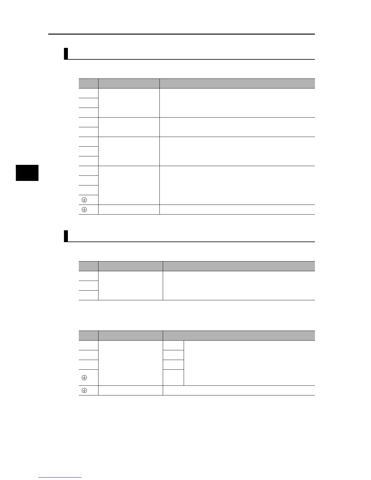
R88D-GT30H/-GT50H
Terminal Block Specifications
R88D-KT06F/-KT10F/-KT15F/-KT20F
Main Circuit Connector Specifications (CNA)
Motor Connector Specifications (CNB)
Symbol
Name Function
L1
Main circuit power supply
input
R88D-KTxH (3 to 5 kW): 3-phase 200 to 230 VAC (170 to 253 V)
50/60 Hz
L2
L3
L1C
Control circuit power
supply input
R88D-KTxH: Single-phase 200 to 230 VAC (170 to 253 V) 50/60 Hz
L2C
B1
External Regeneration
Resistor connection
terminals
Normally B2 and B3 are short-circuited. If there is high regenerative
energy, remove the short-circuit bar between B2 and B3 and
connect an External Regeneration Resistor between B1 and B2.
B2
B3
U
Motor connection
terminals
These are the output terminals to the Servomotor.
Be sure to wire them correctly.
V
W
Frame ground This is the ground terminal. Ground to 100 Ω or less.
Symbol
Name Function
L1 Main circuit power supply
input
R88D-KTxF
(600 W to 2 kW) : 3-phase: 380 to 480 VAC (323 to 528 V) 50/60
Hz
L2
L3
Symbol
Name Function
U Motor connection
terminals
Red These are the output terminals to the Servomotor.
Be sure to wire them correctly.
VWhite
WBlue
Green/
Yellow
Frame ground This is the ground terminal. Ground to 100 Ω or less.

 Loading...