8 Operation
8 - 10
OMNUC G5-series (Pulse-train Input Type) AC Servomotors and Servo Drives User’s Manual
This indicates which control mode is in use: position control or speed control.
This indicates the status of the control input and output signals connected to CN1 pin.
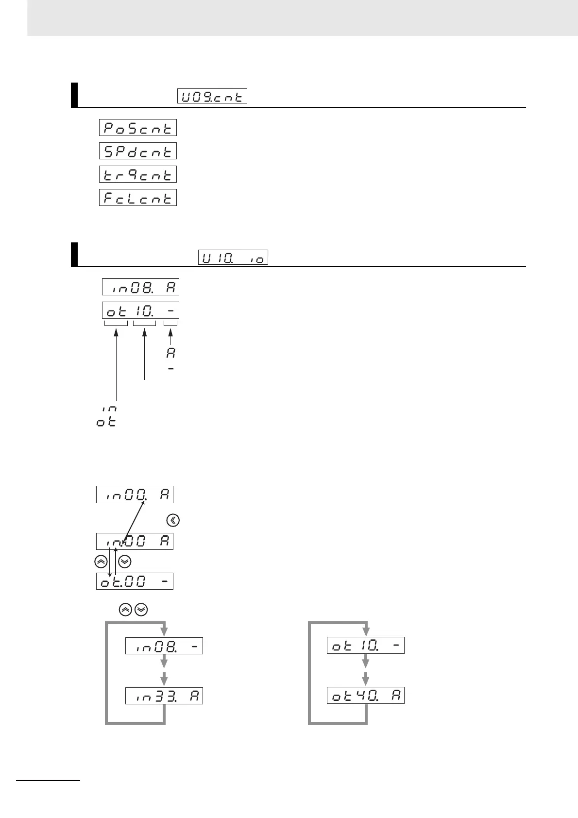
Switching between Input and Output Signals
Control Mode
I/O Signal Status
Position control mode
Speed control mode
Reserved (Do not set any value.)
Reserved (Do not set any value.)
Input signal (Pin No.8) ON
Output signal (Pin No.10) OFF or Disabled.
Pin No.
... Input
... Output
... OFF or Disabled
... ON
It is possible to change the signal number
if the decimal point is located on the right
of the signal number.
It is possible to switch the I/O, if the decimal
point is located on the right of the I/O signal.
Press to move the flashing decimal point.
Switching between Input and Output.
Press to select the signal No. that you want to monitor.
(Highest No. of
Input signal)
(Lowest No. of
Input signal)
(Lowest No. of
output signal)
(Highest No. of
output signal)

 Loading...


