LED indicator
Wiring
Recommended driver:
Type XW4Z-00B manufactured by Omron
Type SZF0-0.4mmx2.5mm
manufactured by Phoenix contact
8
- Insulated ferrule: AWG24 to AWG16 (0.25 to 1.5 mm
2
)
- Crimp height(H): 2.0 mm max Width(W): 2.7 mm max. Conductor length: 8 to 10 mm
When using the twin type ferrule, use equal-sized wires and preferred insulated ferrule.
The twin type ferrule should not be above the adjoining release hole.
●How to insert solid wire and insulated ferrule
The wire should be pushed into the terminal block straight. No need to use the driver.
After inserting, make sure wire is fastened on to terminal block.
●How to release wire
Use the following minus drive to release wire from terminal block.
And
When releasing wire, the power source should be disconnected rst.
1. Push the driver lightly into the taper of release hole.
2. Pull out the wire while the driver is pushed into release hole.
3. Pull out the driver.
Terminal block may be damaged.
1. Not push the driver into the release hole straight.
2. Not push the driver into the release hole by force of 30N and over.
3. Not tip or twist the driver pushed into release hole.
●Precautions for Correct wiring
Fault Detection
When G9SE detects a fault, LED indicators blink to show the information of the fault.
When PWR indicator blinks, check and take needed measures referring to the following table. And then
apply supply voltage to G9SE.
7
PWR
1) Failures involving the wiring of
Safety input 1
1) Failures involving the wiring of
Safety input 2
1) Supply voltage outside the
rated value.
Expected causes of
the faults
Checking points and
measures to take
1) Check the wiring to T11 and T12.
When using stranded wire, insulated ferrule should be used. Use below insulated ferrule.
But do not use ferrule terminals if G9SE is used as UL Listing. Insert the strand or solid wire directly into the
holes on the terminal block.
■Recommended insulated ferrule: manufactured by Phoenix contact
Type
Single
AI 0,34-8TQ
AI 0,5-10WH
AI 0,75-10WH
AI 1-10RD
AI 1.5-10BK
Twin
AI TWIN2x0.75-10WH
Wire size
Cross section(mm
2
) AWG
0,34
0,5
0,75
1,0
1,5
2 x 0.75
22
20
18
18
16
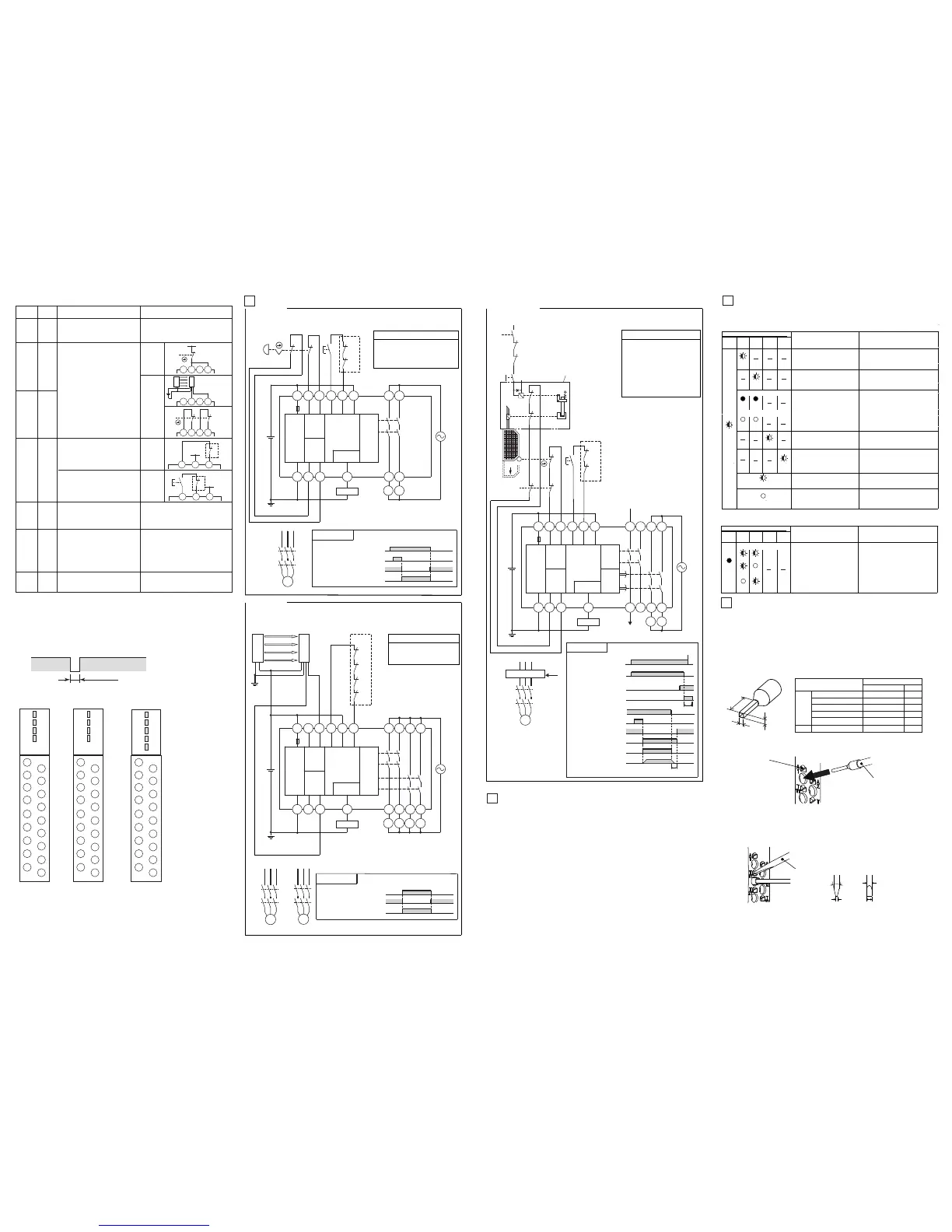
Type G9SE-221-T□
<Guard lock safety door switch (Mechanical Lock)・ 2-channel Safety limit switch inputs
/ Manual reset>
A1
A2
T11 T12 T32 T33
13 23
14 24
T21 T22
T31
X1
24V
PLC etc.
M
KM2
KM1
S1
S3
M
:Safety limit switch
:Contactor
:3-phase motor
Device
Guard lock safety
door switch S2
Operation command
KM1,KM2 N.C. contact
KM1,KM2 N.O. contact
Reset switch S3
Timing chart
37
47
38 48
KM1 KM2
KM2
KM1
S2
KM1,KM2
:Guard lock safety
door switch
(Mechanical Lock)
:Reset switch
S3
Safety limit switch S1
14
Motor controller
Motor controller
(Operation command)
OFF-delay time
Rotation of motor
Blink
2)
Failures of the parts of the circuits
of Safety input 1.
2)
Failures of the parts of the circuits
of Safety input 2.
2) Replace with a new product.
H
W
Release hole
Wire
Front
φ2.5mm
2.5mm
Side
0.4mm
8~12°
Driver
Performance level and safety category (EN ISO13849-1)
Type G9SE can construct the condition conforming to PL=e and category 4 requested by EN ISO13849-1
European standard. This category class is recognized and based on the circuits we made, so we would like you
to conform the category class with G9SE at your application once. Category is judged by the condition of the
whole control system.
・ In order to category 4(EN ISO13849-1)
1) Input the signals to both of the Safety inputs (T11-T12 and T21-T22)
2) Input a signal to the Safety inputs (T11-T12 and T21-T22) through switches with Direct Opening
Mechanism. When using limit switches, at least one of them must have Direct Opening Mechanism.
And wiring must be done in a way that a short circuit between the wires of safety input can be
excluded.
3) When connecting Safety sensor with G9SE, use TYPE 4 safety sensor.
4) Input the signal through a NC contact of the contactor to Feedback/Reset input (T31-T32 for manual
reset or T31-T33 for auto reset).(Refer to '5.Examples of Application')
5) Be sure to connect
the negative terminal of DC power supply to ground.
6) Use two safety outputs (e.g. 13-14 and 23-24) for the system construction.
6
To set Safety outputs in ON state, HIGH
state signals must be input to both of
Safety input 1 and Safety input 2.
Otherwise Safety outputs cannot be
inON state.
To set Safety outputs in ON state, ON
state signal must be input to T33.
Otherwise Safety outputs cannot be in
ON state.
To set Safety outputs in ON state, the
signal input to T32 must change from
OFF state to ON state, and then to OFF
state.
Otherwise Safety outputs cannot
be in ON state.
Turns ON/OFF according to the state of
safety inputs, Feedback/Reset inputs.
During o-delay state, safety outputs
are not able to turn ON.
O-delayed safety outputs.
(See Note1)
O-delay time is set by o-delay preset
switch.
When the delay time is set to zero,
these outputs can be used as
non-delay outputs.
Outputs a signal of the same logic as
Safety outputs
●Wiring of inputs and outputs
Signal
Name
Safety
input 1
Power
supply
input
Terminal
Name
T11,
T12
A1,
A2
Safety
input 2
T21,
T22
Reset/
Feedback
input
T31,
T32,
T33
WiringDescription of operation
1-channel
Safety input
2-channel
Safety input
Auto reset
Manual
reset
Safety
output
13-14,
O-
delayed
Safety
output
Auxiliary
output
X1
Keep these outputs Open when NOT used.
Keep these outputs Open when NOT used.
Keep these outputs Open when NOT used.
The input terminals for power supply.
Connect the power source to the A1 and A2
terminals.
Connect the power supply plus to the A1
terminal.
Connect the power supply minus to the
A2 terminal.
Feedback loop
Feedback loop
T11 T12 T21 T22
+24V
T11 T12 T21 T22
T11 T12 T21 T22
KM
+24V
T31 T33T32
KM
+24V
T31 T33T32
Reset
Switch
23-24,
33-34,
43-44,
37-38,
47-48
●Connecting Safety Sensors and G9SE
640µsMax.
In many case, Safety Sensor outputs include the o-shot pulse for its self test.
The following condition of test pulse is applicable as safety inputs for G9SE.
- O-shot pulse width of the sensor, during the ON-state : 640 μs
(1) When the inputs of G9SE-221-T□ are restored during o-delay time, G9SE-221-T□ will operate
as below. Depending on the reset mode.
- Auto reset mode: Outputs turn o after o-delay time, then immediately turens on.
- Manual reset mode: Outputs turn o after o-delay time, then turn on when reset input is given.
IN1 IN2
OUT
OUT1
OUT2
Blink
Blink
Blink
Blink
The all indicators Blink
Blink
Safety inputs: ON-state
Light
Light
Safety inputs: OFF-state
Light Light
Blink
LED indicator
PWR
IN1 IN2
OUT
OUT1
OUT2
Use the following to wire to G9SE.
- Solid wire: AWG24 to AWG16 (0.25 to 1.5 mm
2
)
- Stranded wire: AWG24 to AWG16 (0.25 to 1.5 mm
2
)
Strip the cover of wire no longer than 8 to 10 mm
Blink
Blink
L
−
Safety sensor
OSSD1 OSSD2
S2
OPEN
S4
S1
KM2
KM1
Guard
Stop signal
Lock
release
signal
S4
:Lock release switch
Lock release signal
Lock release switch S4
Stop signal
Guard closed → opened
Guard can be opened.
●TerminalarrangementandLEDindicators
T33
T32
T31
X1
24
14
T21
23
T22
13
T12
T11
A1
A2
Type G9SE-401 Type G9SE-221-T□Type G9SE-201
PWR
IN1
IN2
OUT
PWR
IN1
IN2
OUT
PWR
IN1
IN2
OUT1
OUT2
T33
T32
T31
X1
44
34
T21
43
T22
33
T12
T11
A1
A2
24
14
23
13
T33
T32
T31
X1
48
38
T21
47
T22
37
T12
T11
A1
A2
24
14
23
13
5
Examples of application
Type G9SE-201
<2-channel emergency stop switch input / Manual reset>
A1
A2
T11 T12 T32 T33
13 23
Safety
Output
(Instant
aneous)
14 24
T21 T22
Reset/
Feedback
Input
Safety
Input1
Power
supply
circuit
Safety
Input2
T31
X1
Auxiliary
output
KM1 KM2
24V
PLC etc.
S1
KM2
KM1
Feedback loop
S2
M
KM2
KM1
S1
KM1,KM2
M
:Emergency stop switch
S2 :Reset switch
:Contactor
:3-phase motor
Device
Note1 : This example is corresponding to category 4
Emergency stop switch S1
KM1,KM2 NC contact
KM1,KM2 NO contact
Reset switch S2
Timing chart
Type G9SE-401
<2-channel safety sensor / Auto reset>
A1
A2
T11 T12 T32 T33
13 23
Safety
Output
(Instant
aneous)
14 24
T21 T22
Reset/
Feedback
Input
Safety
Input1
Power
supply
circuit
Safety
Input2
T31
X1
Auxiliary
output
KM1 KM2
24V
PLC etc.
KM4
KM3
Feedback loop
M1
KM2
KM1
KM1〜KM4
M1,M2
Safety sensor
:Contactor
:3-phase motor
Device
Note1 : This example is corresponding to category 4
Safety sesor outputs
KM1〜KM4 NC contact
KM1〜KM4 NO contact
Timing chart
33 43
34 44
KM3 KM4
M2
KM4
KM3
KM2
KM1
NC
NC
Safety
sensor
ReceiverEmitter
OSSD1
OSSD2
Reset/
Feedback
Input
Safety
Input1
Power
supply
circuit
Safety
Input2
Auxiliary
output
Safety
Output
(Instant
aneous)
Safety
Output
(OFF-
delay)
Feedback loop
Note1 : This example is corresponding to category 4
The all indicators Light o
up
up
o o
1) Check the wiring to T21 and T22.
2) Replace with a new product.
2)
Failures of the parts of the circuits
of Feedback/Reset input.
1)
Failures involving the wiring of
Feedback/Reset input.
1)
Check the wiring to T31, T32, and T33
2) Replace with a new product.
1) Replace with a new product.
1)
Failures of the parts or relays of the
circuits of instantaneous Safety
Output.
1) Mismatch
of the two O-delay
Time Preset Switches.
2)
Failures of the parts or relays of the
circuits of OFF-delay Safety Output.
1) Check
both of the two O-delay Time
Preset Switches.
2) Replace with a new product.
1) Check the supply voltage to G9SE.
1) By excessive electro-magnetic
disturbance.
2) Failures of the parts of internal
circuits
2) Replace with a new product.
1) Check the disturbance level around
G9SE and its related system.
When indicators other than PWR indicator blink while PWR indicator lights up, check and take needed
measures referring to the following table. After removing the fault, turn both safety inputs to OFF state.
Light
up
Safety inputs: ON-state
Light
o
Light
o
Expected causes of
the faults
Checking points and
measures to take
1) Mismatch
between Safety input 1
and Safety input 2.
(OFF timing)
1)
Check the wiring from safety input devices
to G9SE.
Or check the inputs sequence of
safety input devices.

 Loading...


