EasyManuals Logo

Omron ns series Setup Manual

Omron ns series
286 pages
To Next Page IconTo Next Page
To Previous Page IconTo Previous Page
Page #79 background imageLoading...
Page #79 background image
3-7 Installing the Video Input Unit
Connecting to the Console Port Connector
Use the following method to connect the Video Board’s console port connector to the console
connector of an OMRON Vision Sensor (F150-C10V3, F160-C10, F180-C10, F400-C10V2,
F250-C10, V530-R150V2).
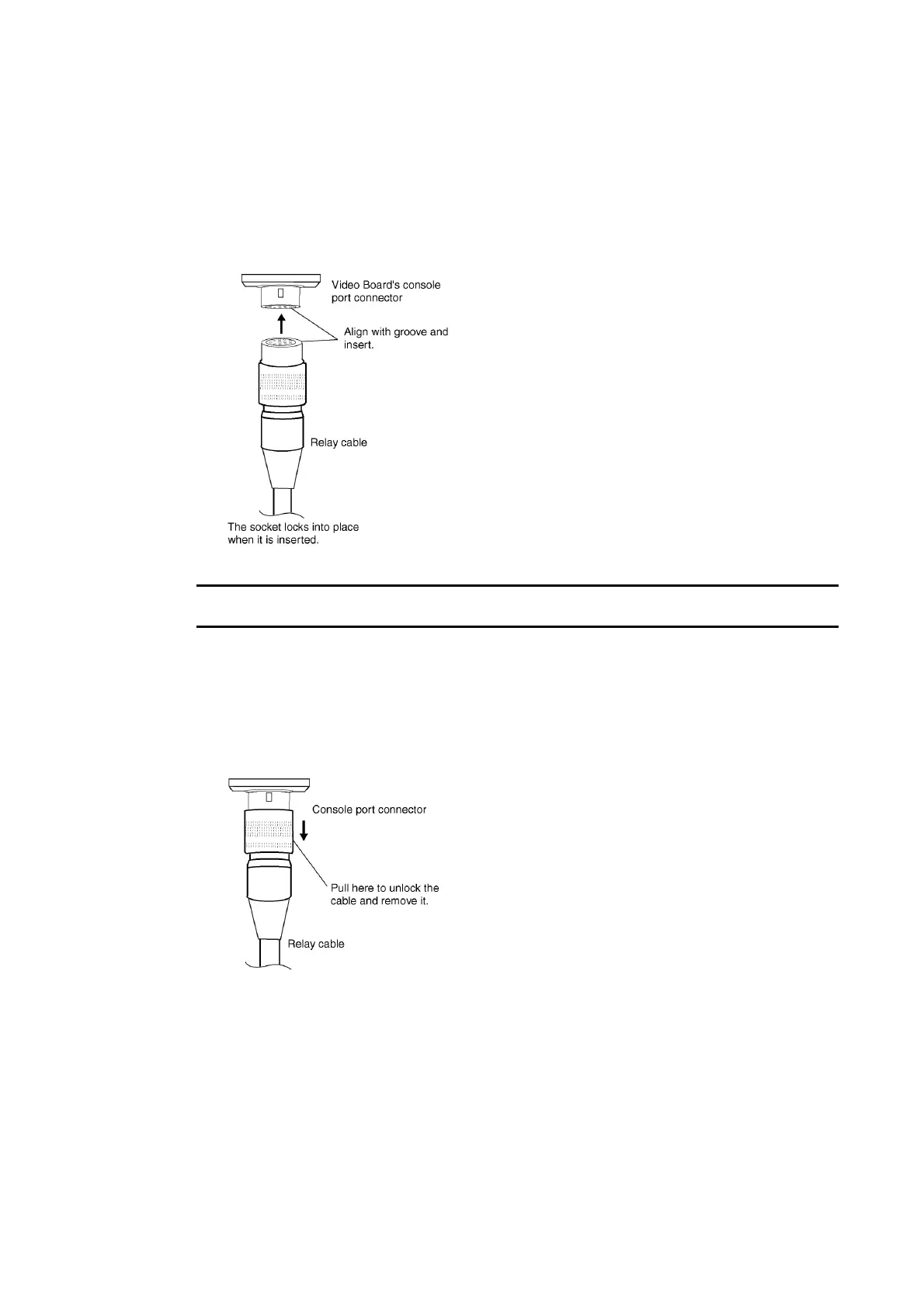
1. Insert the socket of the Relay Cable (F150-VKP; see note) into the Video Board’s console
port connector.
Note The Relay Cable (F150-VKP) is the cable used to connect the Video Board’s console connec-
tor to the console connector of an OMRON Vision Sensor.
Removing the Console Port Connector
Use the following method to remove the Relay Cable from the Video Board’s console port
connector.
1. Remove the Relay Cable by pulling on the connector as shown below.
3-37

Table of Contents

Other manuals for Omron ns series

Questions and Answers:

Question and Answer IconNeed help?

Do you have a question about the Omron ns series and is the answer not in the manual?

Omron ns series Specifications

General IconGeneral
BacklightLED
Power Supply24 VDC
Display TypeTFT LCD
Display Size5.7 to 12.1 inches (depending on the model)
Resolution320 x 240 to 800 x 600
InterfaceEthernet, USB
MemoryVaries by model
Operating Temperature0 to 50°C
Protection LevelIP65 (front panel)
Storage Temperature-20 to 60°C
Humidity10% to 90% (non-condensing)
Shock Resistance147 m/s²
Power ConsumptionVaries by model

Related product manuals