9-14
Mechanical Governor—HGJAB, HGJAC,
HGJAE, HGJAF
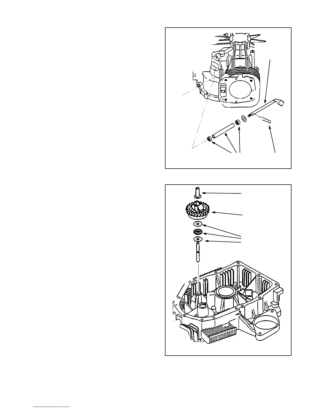
The internal components of the mechanical gover-
nor are accessible when the main bearing cover is
removed. The governor gear assembly rotates on a
shaft projecting from the bearing cover and snaps in
place in the grove in the shaft (Figure 10-1). It is
driven by the camshaft gear. The governor lever is
carried in the crankcase and protrudes out the side
(Figure 9-17), where the governor arm is attached
(Page 8-20). The governor sleeve (Figure 10-1)
pushes up on the paddle of the governor lever shaft
(Figure 9-17). It opposes, in proportion to engine
speed, the force of the external governor spring
(Page 8-20).
Be careful when assembling the main bearing cover
to the crankcase that the governor and camshaft
gears mesh properly. If necessary, poke a thin rod
through the gap between crankcase and cover to
turn the governor gear slightly so that the teeth
mesh.
GOVERNOR
LEVER
SHAFT
SNAP
PIN
NEEDLE BEARINGS
AND SPACER
FIGURE 9-17. GOVERNOR LEVER
GEAR & FLY-
WEIGHTS
GOVERNOR
SLEEVE
THRUST
BEARING AND
WASHERS
FIGURE 9-18. GOVERNOR GEAR
 Loading...


