OPTIONAL
EQUIPMENT
Only
the most
popular
options are
discussed
here.
Time Deloy Reloys:
A
time delay
is often
required
in one
or more of the control
functions such
as
engine
starting,
load
pickup,
engine stopping,
load transfer
to commercial
line. Two different types
of relays are used,
depending
on
the
function to
be
delayed and
the
required delay
period.
(See
Adjustnents
in the
Maintenance Section
for
complete
relay
delay descriptions.)
Tine
Delay on
Staftin(: Delays
plant
starting
after
a
power
failure.
It
prevents plant
operatiorr during very short
line
failures.
Time
Delay on
Load
Pickup: Delays
the
transfer
of
the load
to
allow
for
plant
warm up.
Tine
Delay
on Re-frans/er:
Allows
time
for
the
returning
commercial power
to
stabilize before connecting
it
to
the
load.
The
plant
supplies
power
during
this
period.
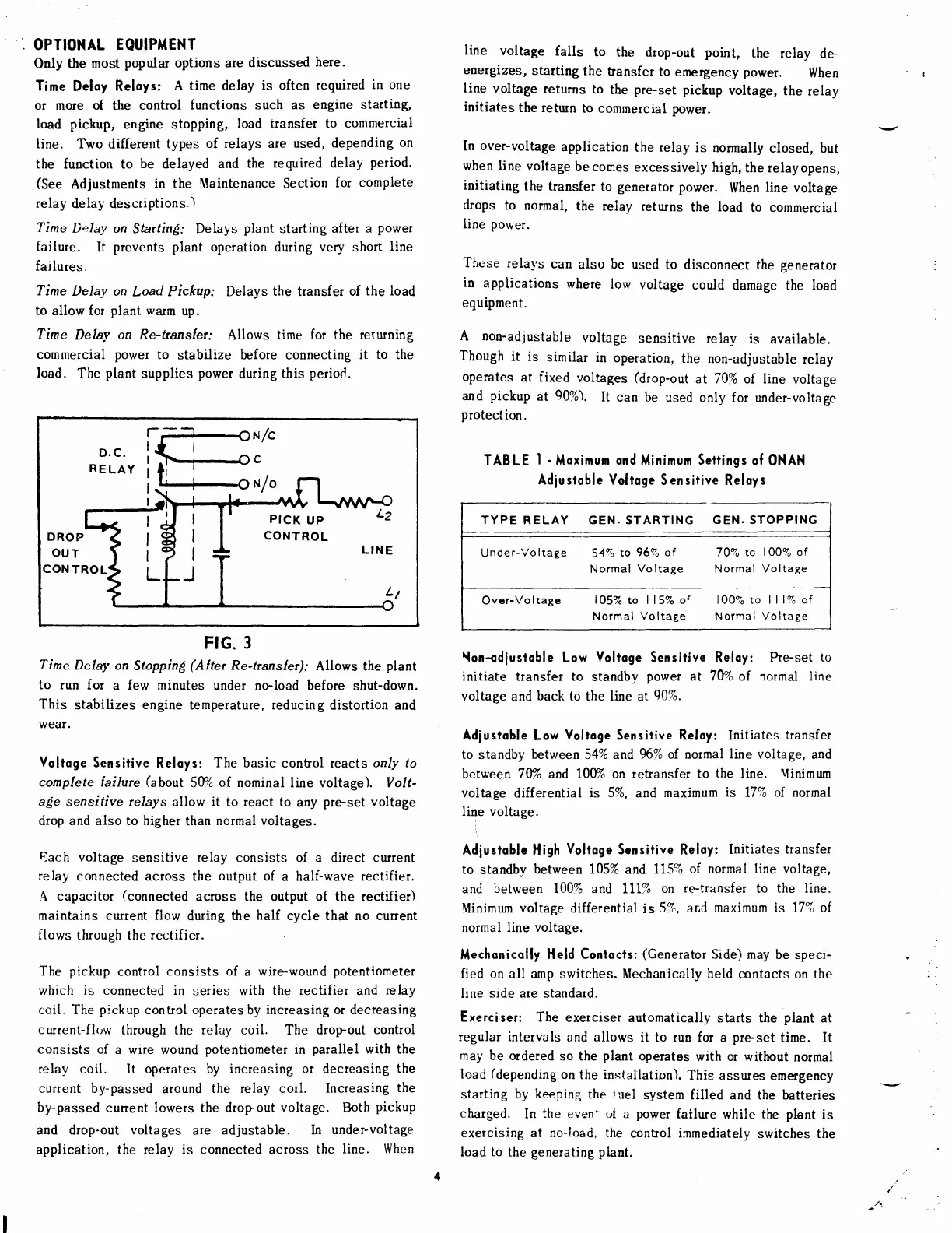
FIG.3
Time
Delay on
Stoppin(
(A|tet
Re-/rans/er);
Allows the
plant
to run for
a
few minutes
under
no-load
before
shut-down.
;!;
stabilizes
engine
temperature,
reducing
distortion and
Voltoge Sensitive
Reloys:
The
basic conhol reacts
only to
complete failure
(about
5V"
of.
nominal line voltage). Volt-
a6!e sensi tive
relays
allow
it
to react to
any
pre-set
voltage
drop and also
to
higher
than
normal
voltages.
Each
voltage
sensitive
relay
consists
of
a direct
current
relay
connected across
the
output
of
a half-wave
rectifier.
.q
capacitor
(connected
across the output of the
rectifier)
maintains current flow
during
the
half
cycle that no cunent
flows
through
the
re,ctifier.
The
pickup
control
consists of
a wire-wound
potentiometer
which is connected in
series with
the rectifier
and
relay
coil. The
pickup
control operates
by
increasing
or decreasing
current-flr-,w
through the
relay
coil. The
dropout control
consists of
a wire wound
potentiometer
in
parallel
with the
relay
coil.
It
operates
by
increasing or
decreasing
the
current by-passed
around
the relay coil. Increasing
the
by-passed
cunent
lowers
the dropout
voltage. Both
pickup
and
drop-out voltages
are
adjustable.
In
under-voltage
application,
the
relay is
connected
across
the
line. When
line
voltage
falls
to
the drop-out point,
the relay
de-
energizes,
starting
the hansfer
to
emergency
power.
When
line
voltage
returns
to
the
pre-set
pickup
voltage,
the
relay
initiates
the return
to commercial
power.
In
over-voltage
application
the
relay
is
normally
closed, but
when line
voltage
becomes
excessively
high,
the relayopens,
initiating
the
transfer
to
generator
power.
When
line
voltage
drops to
normal,
the relav
returns
the load
to commercial
line
power.
Ttrese
relays
can
also
be
used
to
disconnect the
generator
in
applications
where low
voltage
could
damage the
load
equipment.
A non-adjustable
voltage
sensitive relay
is
available.
Though
it
is
similar
in
operation,
the non-adjustable
relay
operates
at fixed
voltages
(drop-out
at
70%
of line
voltage
and
pickup
at
90%).
[t
can
be
used
only
for under-voltage
protection.
TABLE
I
-
Moximum
ond
Minimum
Seilings of
0NAN
Adiustoble
Voltoge S
ensitive
Reloys
Non-odiustoble
Low
Voltoge Sensitive Reloy: ke-set
to
initiate
transfer to
standby
power
at 70%
of
normd line
voltage
and
back
to the line
at
90%.
Adiustoble
Low Voltoge
Sensitive Reloy:
Initiates
transfer
to standby
between
54% and
96% of. normal
line voltage,
and
between 7Vo
and l\Vo on
retransfer
to
the
line.
Minimum
voltage
differential
is 5%, and
maximum
is
17%
of normal
line voltage.
Adiusloblc
High
Voltoge
Sensitive
Reloy:
Initiates
transfer
to
standby
between 105%
and llSvo
of
normal
line voltage,
and
between
100% and lll%
on
re''transfer
to
the line.
Minimum
voltage differential
is
5%, and
maximum
is 17qo of.
normal line
voltage.
Mechonicolly
Held Contocfs:
(Generator
Side)
may be speci-
fied on all
amp
switches.
Mechanically
held
contacts
on
the
line
side
are standard.
Exerciser: The
exerciser automatically
starts the
plant
at
regular
intervals
and
allows
it to run
for a
pre-set
time. It
may be
ordered so the
plant
operates
with
or without
normal
load
(depending
on
the
installation).
This assrues
emergency
starting by
keeping
the
luel
system
filled and
the batteries
charged.
In
the
even:
of
a
power
failure
while
the phnt
is
exercising at no-load, the
conhol
immediately
switches the
load
to
the
generating
plant.
x/c
c
N/o
PICK
UP
CONTROL
L2
DROP
OUT
LINE
L1
CONTROL
TYPE
RELAY GEN. STARTING
GEN.
STOPPING
Under-Voltage
54vo
to 96%
of 70Vo to
100% of
Normal
Voltage Normal
Voltage
ioor" . ilt"
"t
Over-Voltage
105%
to
l15% of 100?o to lll%
o
Normal
Voltage
Normal
Voltage
 Loading...