16User ManUal v1.6
STEP 15: In-Depth Troubleshooting
If your coil is under-performing or not turning on and you want to do some detailed
troubleshooting, read on. You can also perform these steps if you want to verify that your
coil is constructed properly before powering it up fully, such as when you’re waiting for
your secondary’s varnish to dry.
A. Check for GDT Buzz
Verifying whether you can hear the gate drive transformer vibrate at the interrupter
frequency will help you narrow down your problem to the board’s logic vs. the board’s
power components or the resonator. To view a tutorial showing exactly how to do this,
visit http://onetesla.com/tutorials.
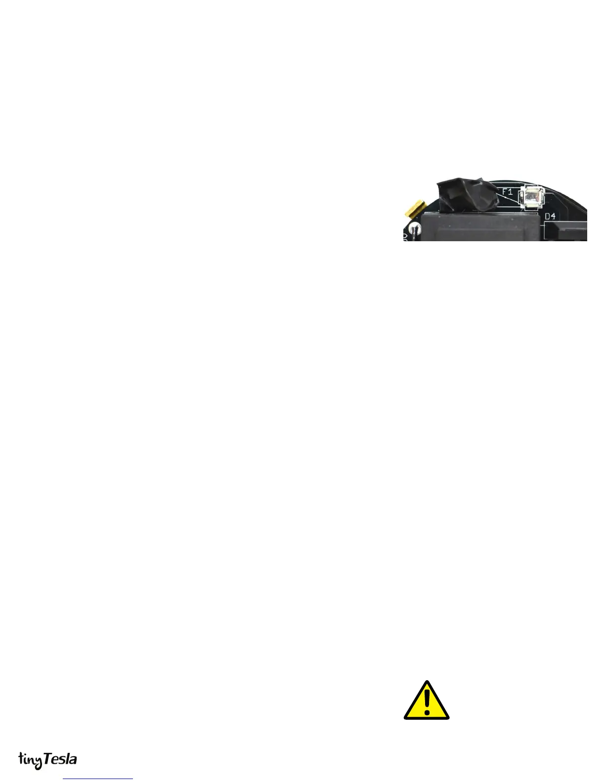
i. REMOVE THE FUSE and cover the left fuse holder with electrical tape.
Removing the fuse de-energizes the power side of the board. This fuse clip
becomes electrically hot when you plug in the board to AC power, so you want
to cover it with tape to prevent yourself from accidentally touching it.
ii. Start up the coil following the startup and shutdown procedure in step 15.
Verify correct operation of your interrupter, then connect your interrupter to the
coil, then connect your AC adapter to your coil, then plug in the AC adapter.
iii. Play a tone or song using the interrupter and listen closely to the board. You
should hear the tone playing faintly from the GDT. Note that it’s a faint sound,
so you need to be in a quiet environment!
If the GDT is buzzing then your board’s logic half is most likely working. The problem lies
in the power components, the antenna connection, or the resonator.
B. Check for Warm Spots
You can learn a lot without even pulling out your multimeter from checking whether
components on the board get hot.
Once your board is unplugged and you have waited for 5 minutes to allow the bus
capacitors to discharge, check whether the ICs or regulators are hot. If an IC is hot, it
could be damaged. If the 5V regulator is hot, then you know that a component that is
powered o of 5V has failed short, or there’s a solder bridge that’s causing a short along
the 5V rail. The same thing goes for the 15V regulator. If you remove the suspected IC
and the regulator is still hot, you know that either the regulator is damaged or you have a
solder joint. It’s possible that the IC was damaged as well.
If an electrolytic capacitor is hot, it’s installed backwards. Don’t touch the tops of the bus
capacitors (47 uF) if their tops are metal! If you didn’t install your 100kΩ bleeder resistors
properly or didn’t wait long enough, they may still be energized!
C. Troubleshooting with a Multimeter
Disassemble the coil down to just a driver board mounted on a heatsink. REMOVE THE
FUSE and cover the left fuse holder with electrical tape. Removing the fuse de-energizes
the power side of the board. This fuse clip becomes electrically hot when you plug in the
Remove the Fuse to Separate Logic and Power
When debugging, you want to separate your
board’s logic from its power components. Always
remove the fuse and cover the fuse clips in
electrical tape!
Every problem has a cause!
Remember that every problem has a cause.
Components are very rarely dead upon arrival.
Blindly replacing chips can lead to a whole lot more
dead chips if you don’t nd the root cause!
What’s a “voltage rail?”
The 5V and 15V rails are all the points on the circuit
board that should be at 5V and 15V, respectively.
They’re commonly called “rails” because these
points are connected to each other, they all carry
the same voltage and they all supply power to
components that need 5V or 15V.
 Loading...