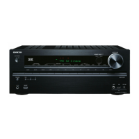
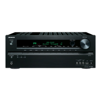
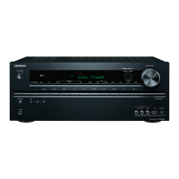
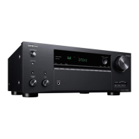
TX-NR717/818/ DTR-40.4/50.4
OPERATION CHECK-1
1.OPERATION CHECK(1/3)
1-1. OPERATIONS OF SPEAKER RELAYS
The relay shall be ON about 10 seconds after POWER is ON and shall be OFF immediately after POWER is OFF.
1-2. OPERATIONS OF VOLTAGE-DETECTION PROTECTORS.
See “OPERATION CHECK-4, -6” for TEST MODE operation.
NOTE: Don't connect load nor short speaker terminals.
(How to check in test mode)
a. Change the state to "TEST 4-24".
b. It tests by being automatic in order of TEST 4-24(FL+) → 25(FR-) → 26(C+) → 27(SL-)
→ 28(SR+) → 29(SBL-) → 30(SBR+) → 31(FHL-) → 32(FHR+). If TEST 4-32 is ok, it becomes the display of "TEST 4-42."
c. It will complete, if displayed on FL TUBE as "TEST 4-42."
1-3. OPERATIONS OF CURRENT-DETECTION PROTECTORS
See “OPERATION CHECK-4, -6” for TEST MODE operation.
a. Change the state to "TEST 4-42".
Even if you connect 3-ohm load for every channel of L, R, C, SL, SR, SBL and SBRch, a relay should not cut off.
b. If 1-ohm load is connected for every channel of L, R, C, SL, SR,SBL and SBRch, a relay should hold the state of ON.
1-4. CONFIRMATION OF RDS (RADIO DATA SYSTEM) OPERATION
(applies to MMA/MMP/MMQ/MMR Type. )
a. Input 98MHz,30dBμ signal modurated with RDS data.
b. When a PS information is received, the name of the station "RDS TEST" shall be displayed within 2 seconds instead of the frequency.
1-5. CONFIRMATION OF HEAD PHONE OPERATION.
Confirm the Listening Mode is automatically switched to "STEREO" mode when headphones plug is inserted into the PHONES jack.
1-6. CONFIRMATION OF 12V TRIGGER OPERATIONS .
See “OPERATION CHECK-4, -5” for TEST MODE operation.
a. After checking that there is no output from 12V TRIGGER ZONE2(Integra model is TRIGGER A) terminal, confirm that
there is an output of 12V±10%/150mA mmediately switched the "TEST2-11". (except TX-NR717MJJ/818MJJ)
b. After checking that there is no output from 12V TRIGGER ZONE3 (Integra model is TRIGGER B) terminal, confirm that
there is an output of 12V±10%/ 25mA after 2 seconds switched the "TEST2-12". (except TX-NR717MJJ/818MJJ)
c. After checking that there is no output from 12V TRIGGER C terminal, confirm that there is an output of 12V±10%/ 25mA after 2 seconds
switched the "TEST2-13". (only DTR-40.4/50.4)
1-7. CONFIRMATION OF OUTPUT VOLTAGE SENSOR AND THERMAL PROTECTOPERATION.
a. Set the TEST MODE to "TEST 4-43". Confirm to lit "FM STEREO" on FL displaythe .
Confirm the relays RL6901/6902(TX-NR818, DTR-50.4) is OFF immediately .
Confirm the relays RL691/692(TX-NR717,DTR-40.4) is OFF immediately .
b. Push STANDBY/ON button while pushing down DISPLAY button to display CPU PROGRAM version.
Push TONE button while displaying CPU PROGRAM version to display value of temparature sensor.
Regarding to "AT" and "DT" of display value, confirm outside temperature ±20C is displayed immediately after energizing.
No singal condition (Ex. Display)
V:>00 F:x S:H
AT:020 DT:020
V: Output signal level
F: FAN condition
S: Amplifier power supply voltage condition
AT: Temparature sensor of Amplifier
DT: Temparature sensor of HDMI PWB
 Loading...