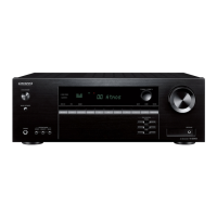
TX-SR701/E
MAIN MICROPROCESSOR
TERMINAL DESCRIPTION
No. S
in
2 YCSEPCLK O Not used.
3 OSDCS O Serial communication chi
in for OSD IC Q204.
4 OSDDA O Serial communication data out
in for OSD IC.
5 OSDCLK O Serial communication clock out
in for OSD IC.
6 Evdd Power su
in
8 VFSDA O Serial communication data out
in for video select switch IC Q205.
9 VFSCLK O Serial communication clock out
in for video select switch IC.
10 VFSSTB O Serial communication strobe out
in for video select switch IC.
11 Z2PMUT O Mutin
ut.
12 DSP1HDOUT I Serial communication data in
in from first DSP IC Q700.
13 DSPSDO O Serial communication data out
in for DSP and DIR ICs.
14 DSPCLK O Serial communication clock out
in for DSP and DIR ICs.
15 T12VZ2 O 12V tri
in for zone 2.
16 T12VA O 12V tri
ure audio
21 Z2LMUT O Line out
in for zone 2
22 Z2MUT O Mutin
in for zone 2
23 AMUT O Audio mutin
in
24 PLLSTB O Serial communication strobe out
ack.
25 PLLDA O Serial communication data out
in for PLL IC.
26 PLLCLK O Serial communication clock out
in for PLL IC.
27 TMUT O Mutin
ack.
28 AFSSTB O Serial communication strobe out
in for select switch IC Q301.
29 AFSSCK O Serial communication clock out
in for select switch IC Q301.
30 AFSDA O Serial communication data out
in for select switch IC Q301.
31 ~RESET I S
ut
32 XT1 Not used.
33 XT2 Not used.
34 REGC Re
in
35 X2 Main clock connection
36 X1 Main clock connection
.
39 CLKOUT Not used.
40 Z2PSELCLK O Clock out
in for zone 2. Not used.
41 Z2PSELDA O Data out
in for zone 2. Not used.
42 Z2PSELMUT O Select mutin
in for zone 2. Not used.
43 SELMUT O Mutin
rocessor IC Q302.
44 SELCLK O Serial communication clock out
in for Q302 and Q310.
45 SELDA O Serial communication data out
in for Q302 and Q310.
46 Z2SELMUT O Mutin
in for volume control IC Q310.
47 CODECINT I Error detection in
in for DIR IC Q800.
48 ~CODECCS O Serial communication chi
in for DIR IC.
49 CODECSDI I Serial communication data in
in for DIR IC.
50 ~DSP1RST O Reset si
in for first DSP IC Q700.
 Loading...